Project Dump
Requirements
- Design a lunar phases tracker that can be used to display the data from the farmSense API
- Use a stepper motor to control the movement of the display
- Use a microcontroller to control the stepper motor and get data from the farmSense API
- Use a PCB to connect the microcontroller and the stepper motor
- Use Different Manufacturing Processes to create the parts of the Lunar Tracker
- Diaply the Phases of the moon while showcasing the date and the lunar phase on a LCD.
Softwares 💻
- Fusion 360
- PrusaSlicer
- Kicad
- Mods
- Arduino IDE
Cardboard Prototyping
I started first with making the prototype which I documented in my system integraion week
BOM & Project Tracking
I documented the BOM & project tracking system & ToDos for my final project in my Application & Implication week
Design Flow
Then I used Fusion 360 for the Design.
-
Sides
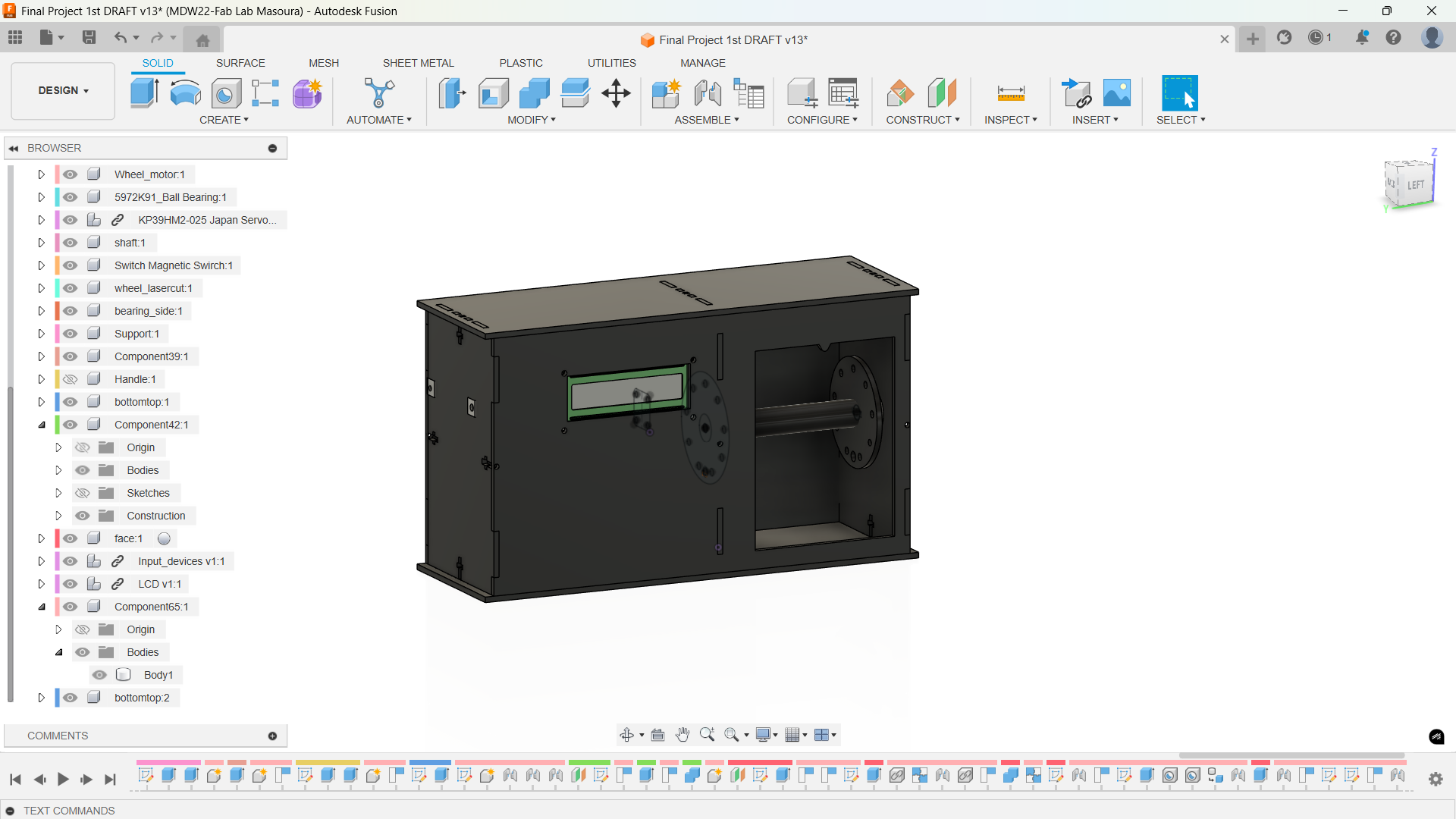
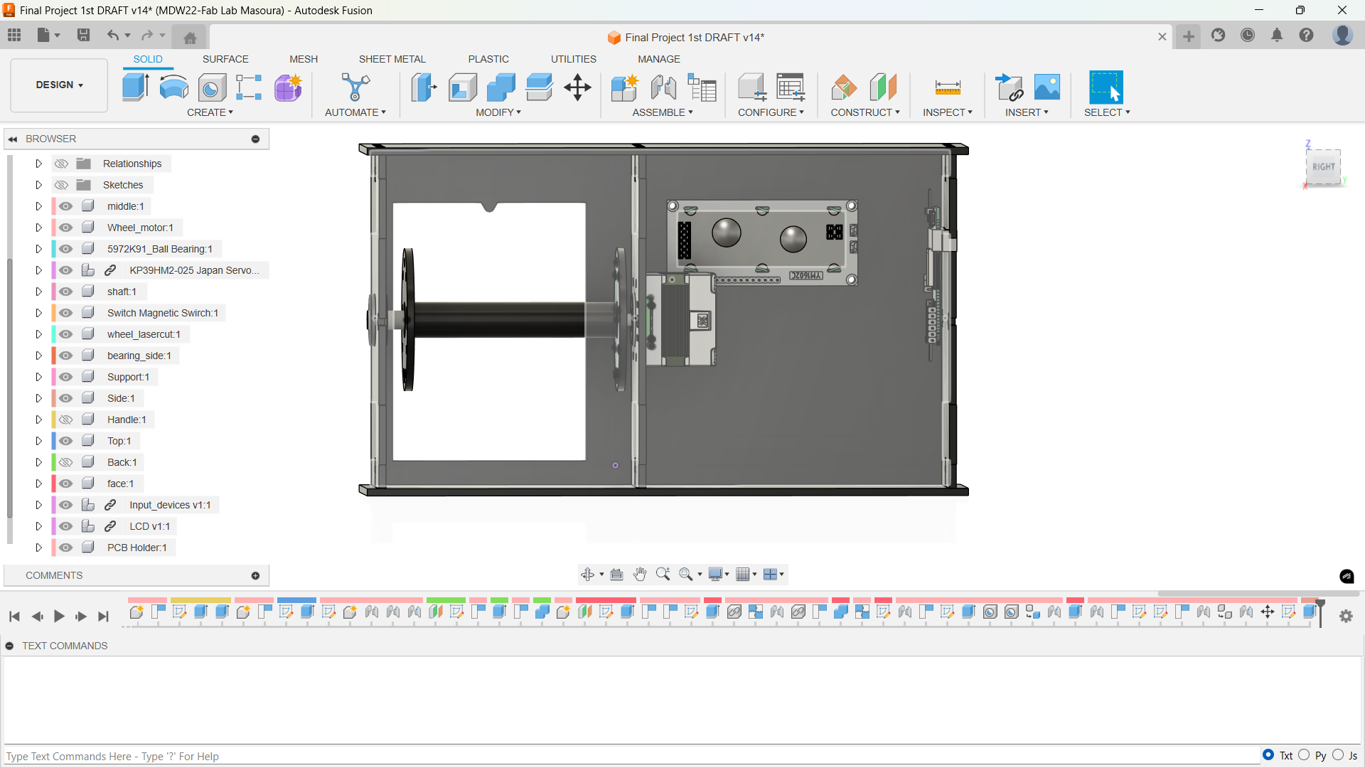
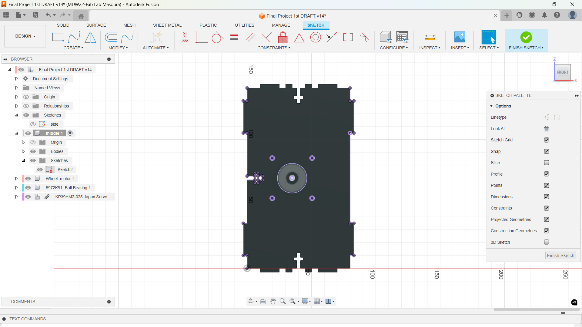
I sketched the side first since I would make two compartmanets in the design one for the electronics and one which will have the phases and the mechanism
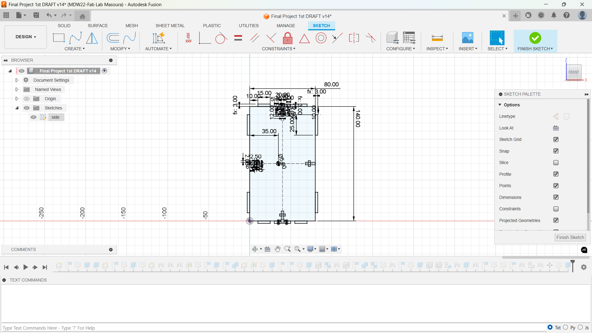
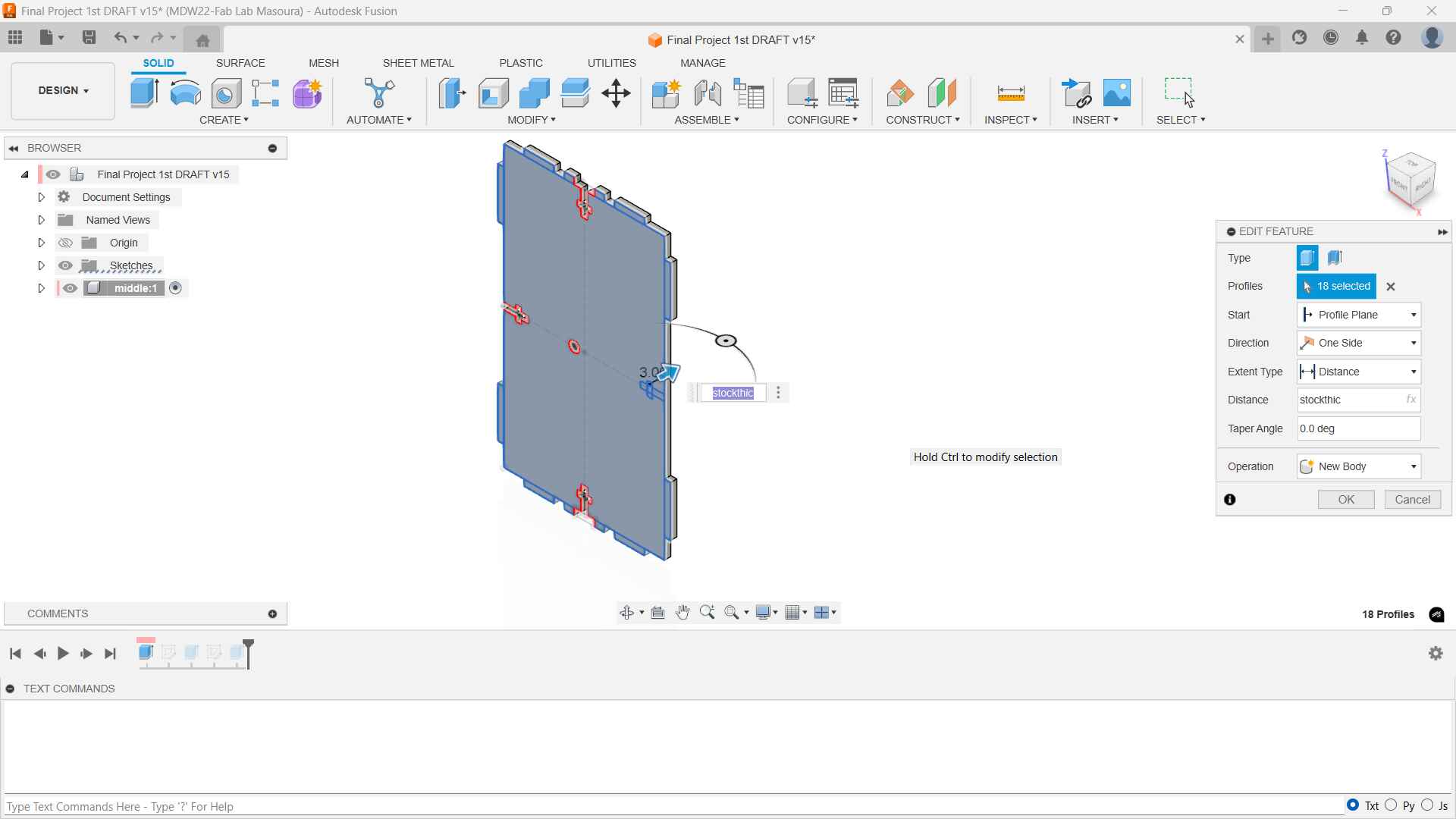
I created 3 Sides from this initial sketch: the motor and reed switch side which is in the middle and one carrying the bearing and one that has two holes for the pcb holder clip. Here're the sketches.
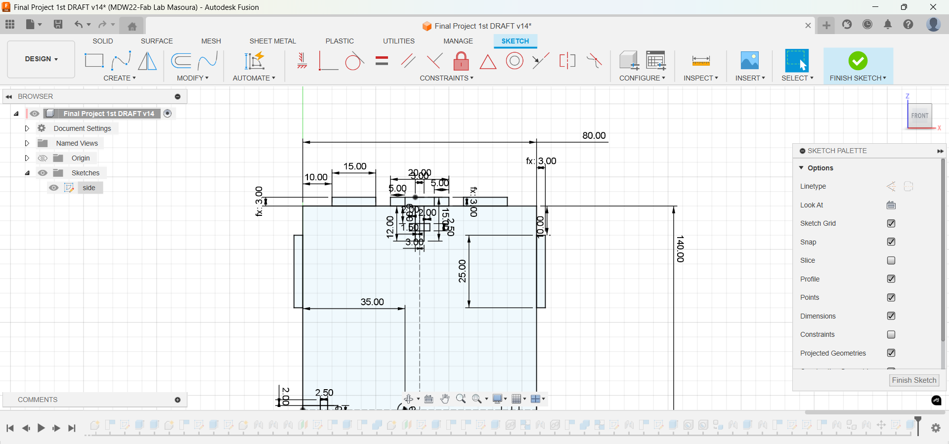
Middle Side
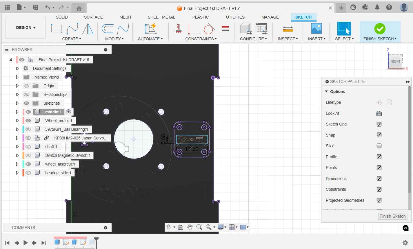
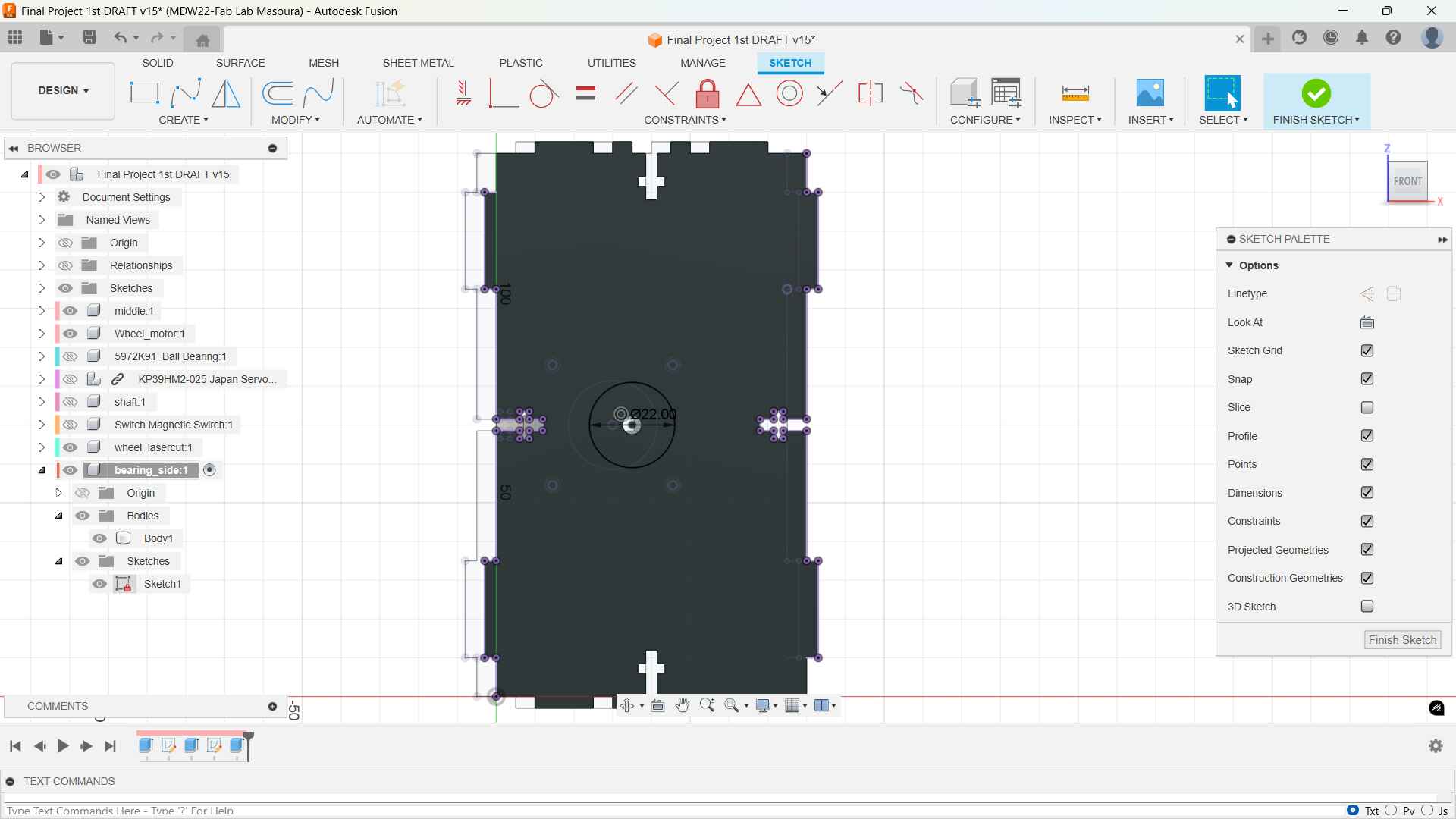
Bearing Side
I inserted a bearing with 8mm hole from McMaster Library and I jointed the bearing to the hole.
.jpg)
PCB Side
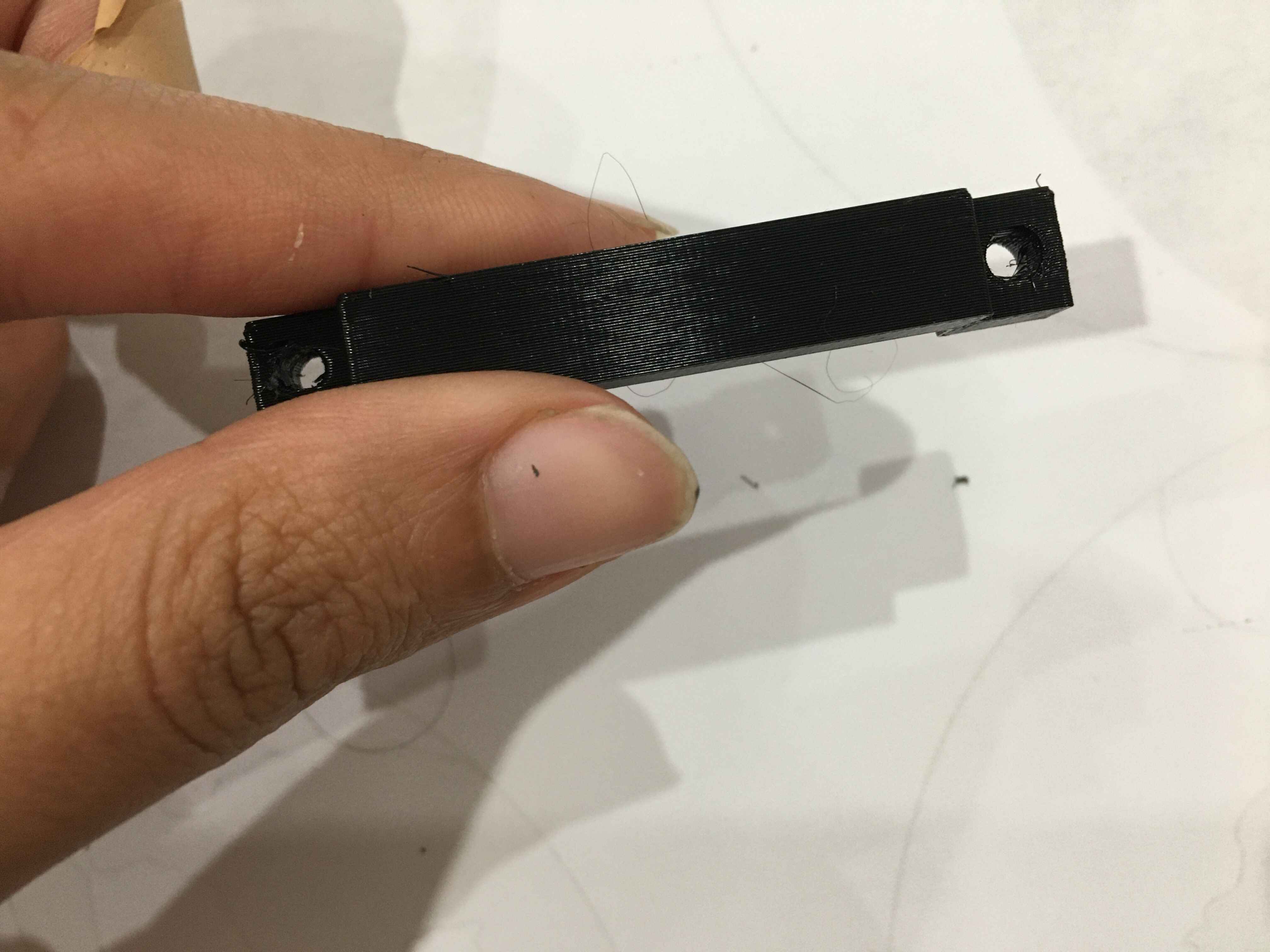
For this side I designed a pcb fixer since the space would be packed with wires and the other stepper pcb. Here're the sketches and procedures: sketch, extrude, hole, and project, extrude cut
-
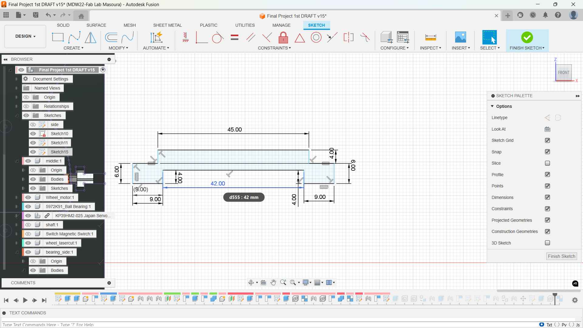
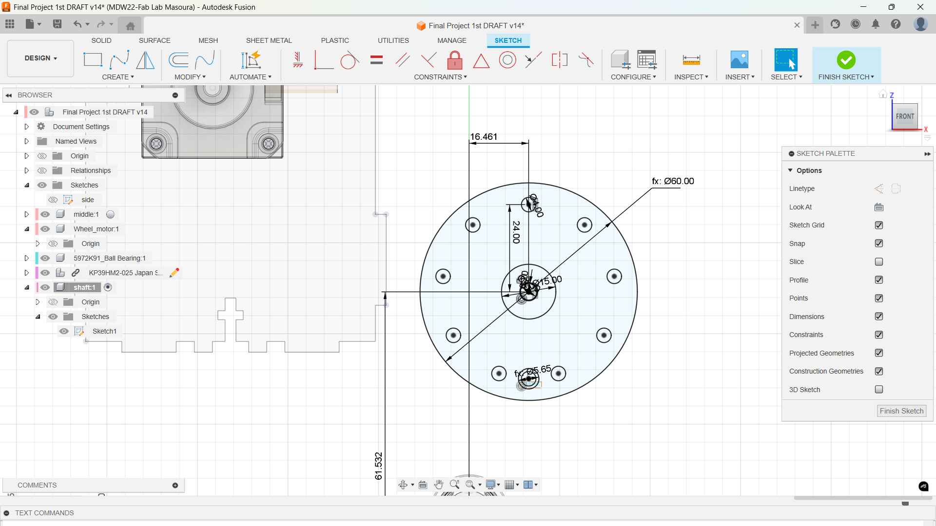
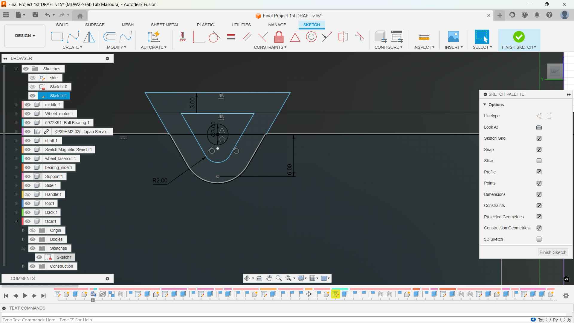
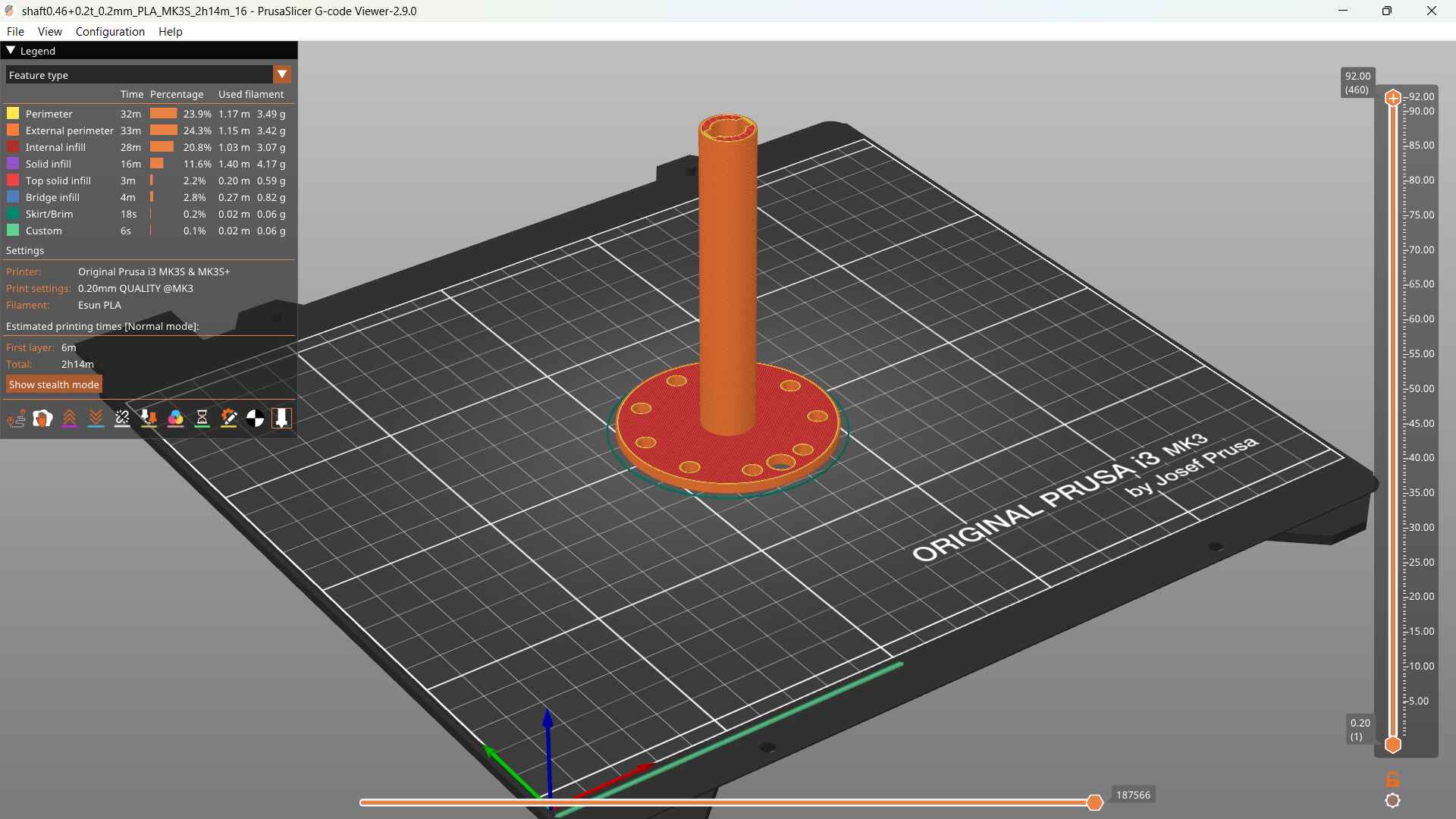
Shaft & Support
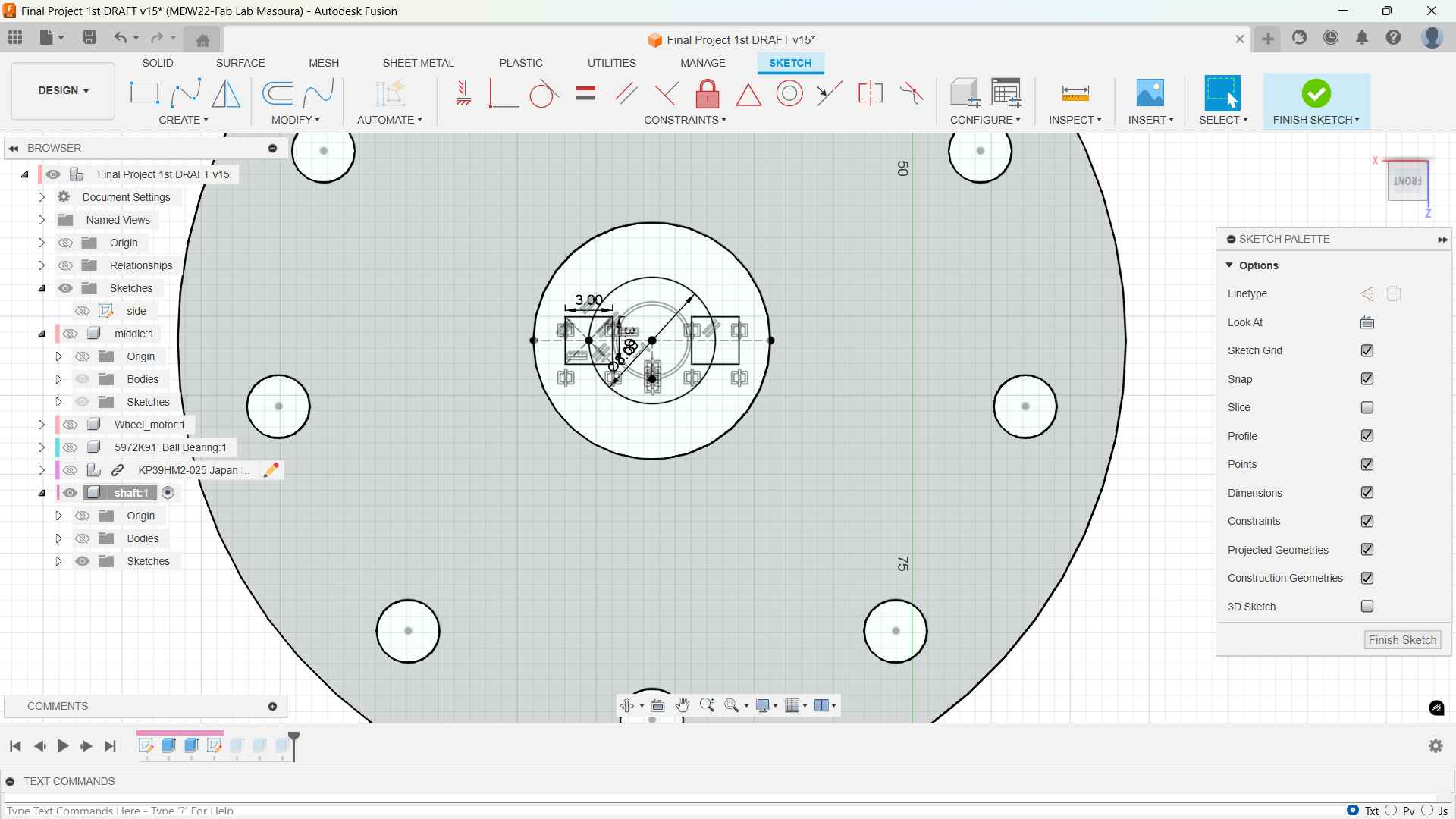
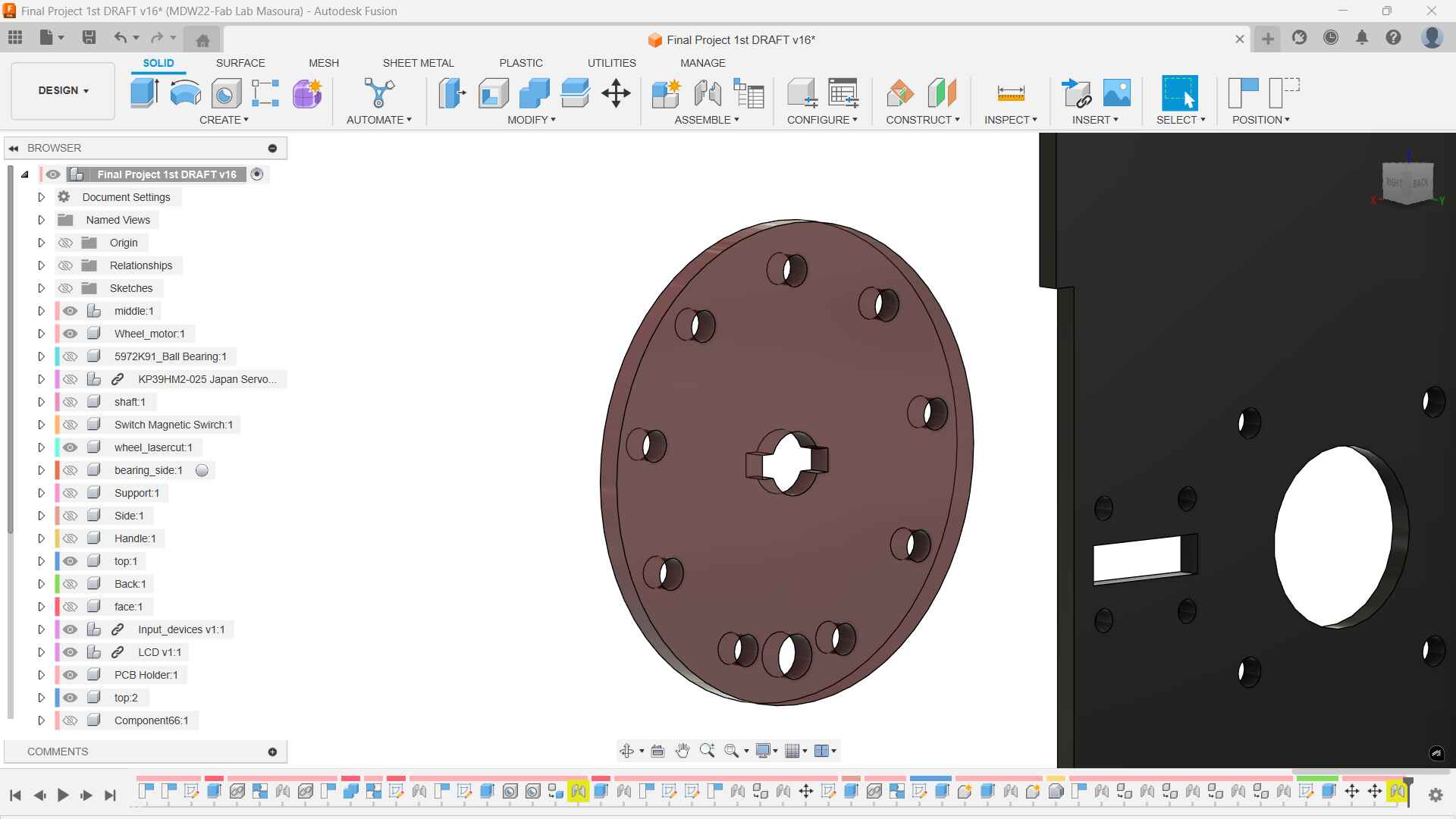
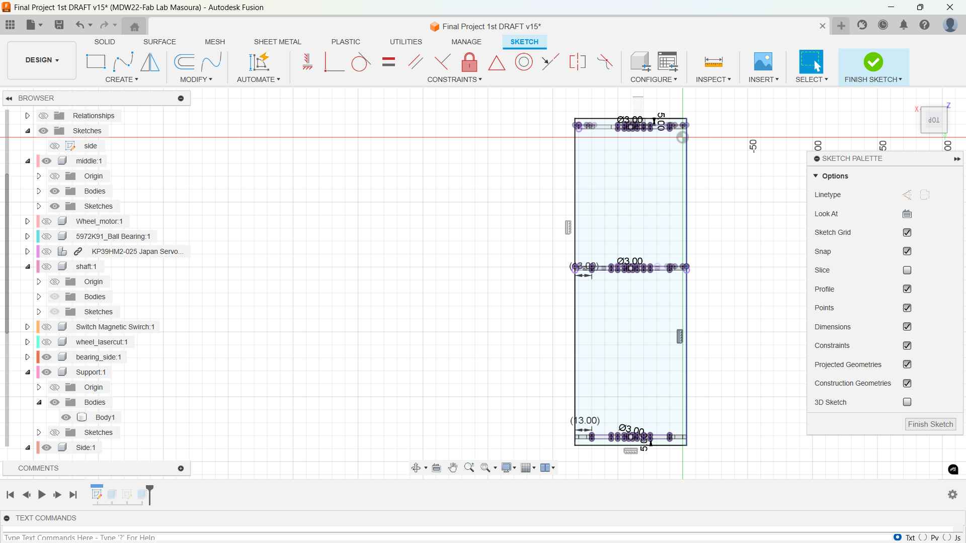
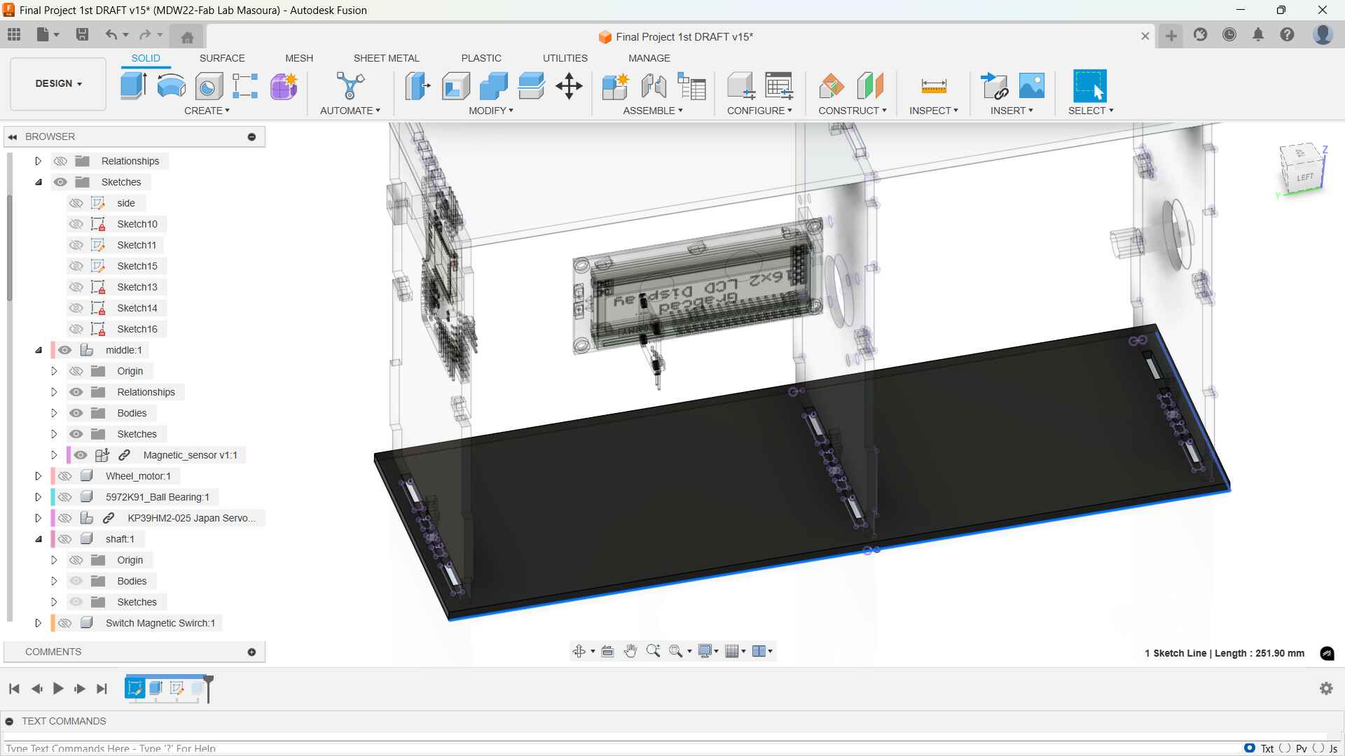
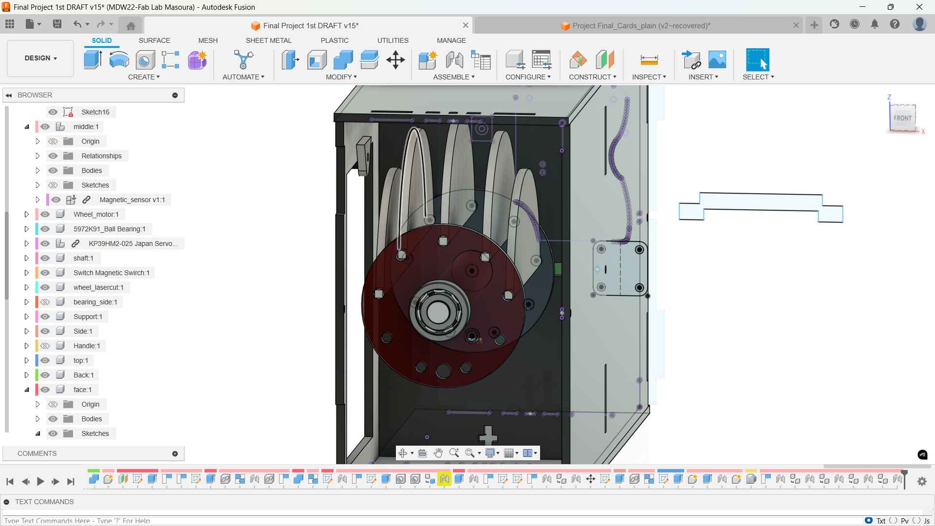
i sketched first the circle and projected the motor shaft and add a circle pattern for 9 flaps: 8 for the phases and one for the homing flap. I also added a bigger circle for the magnet that will be detected by the reed sensor and then the motor would stop.
I wanted to make the other side of the shaft laser cut to cut down on the 3d printing supports so I projected the same circle but then I added a support piece that has a configuration this will act as a lock to lock the laser cut mirrored shaft disc in place.
The configuration
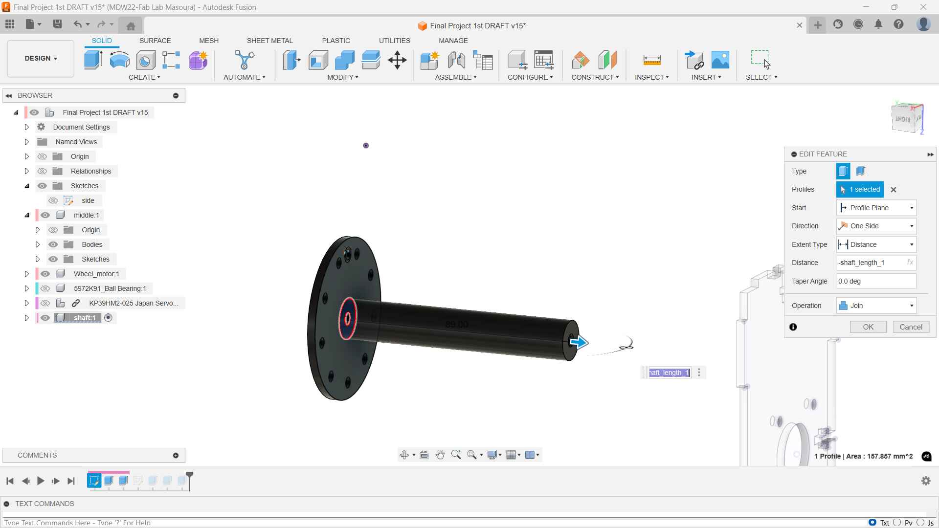
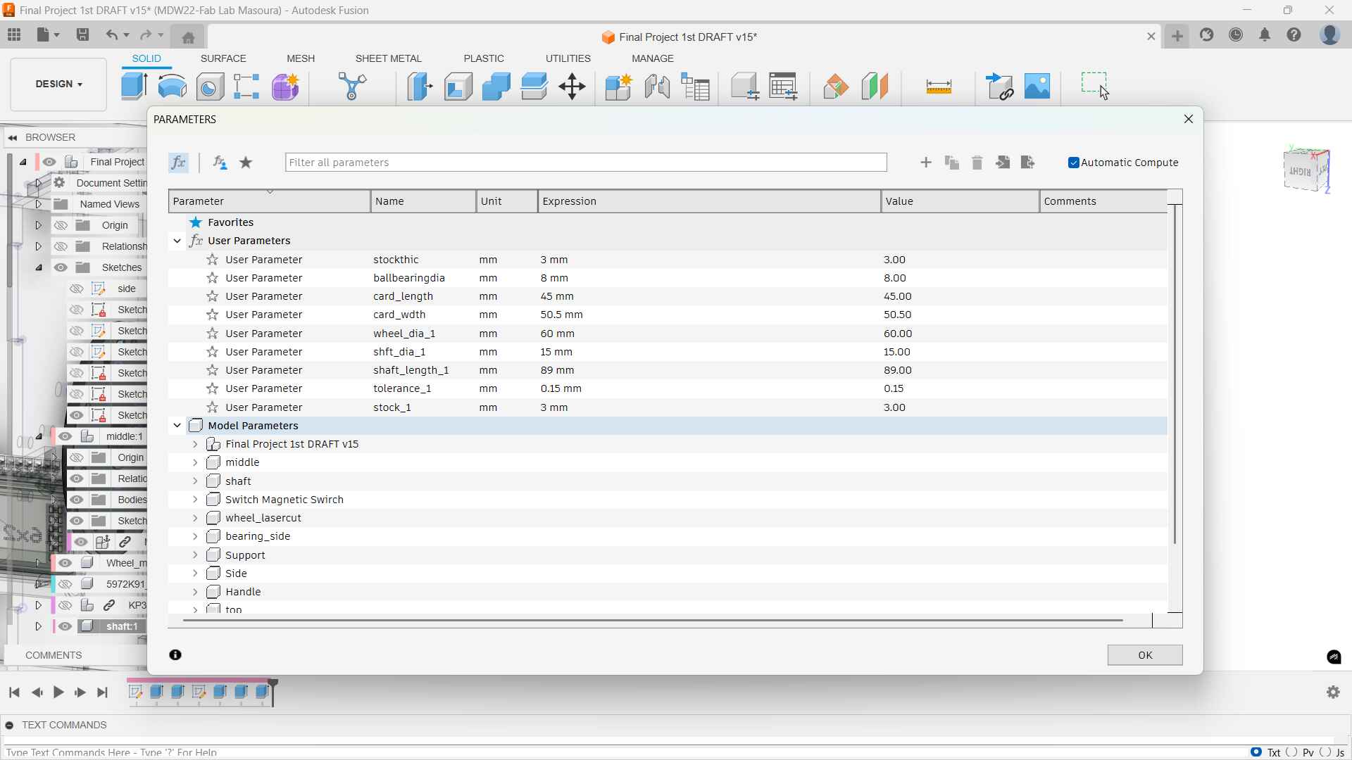
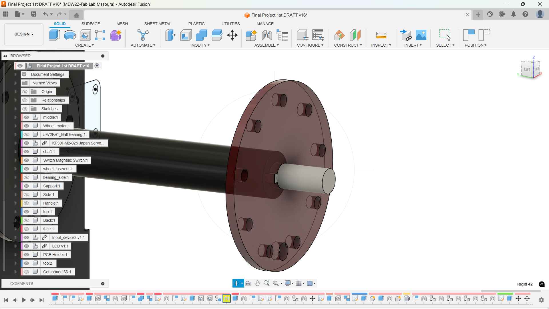
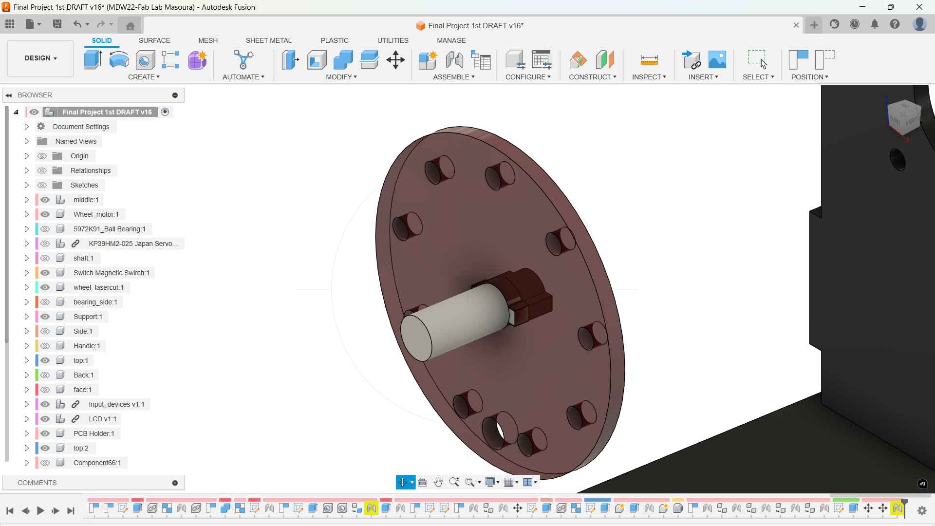
Here's the extrusion and the parameters to control the shaft length
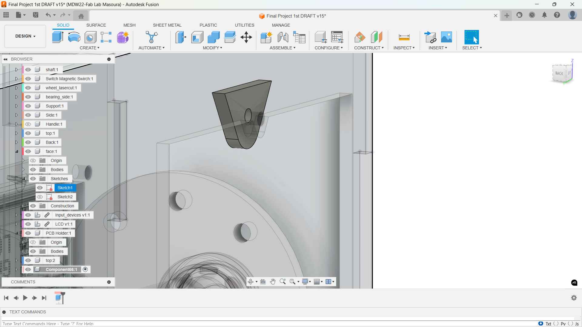
Support 3D view
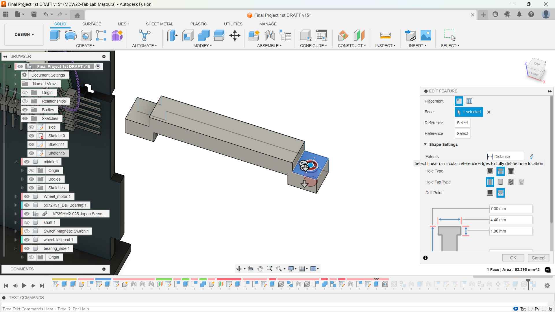
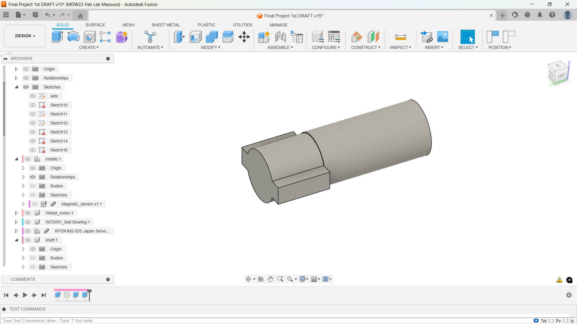
Laser Cut wheel
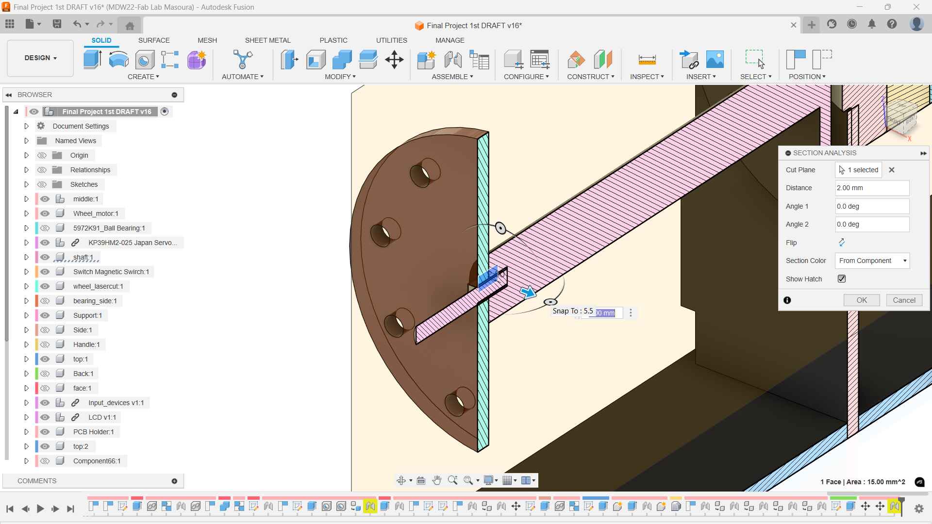
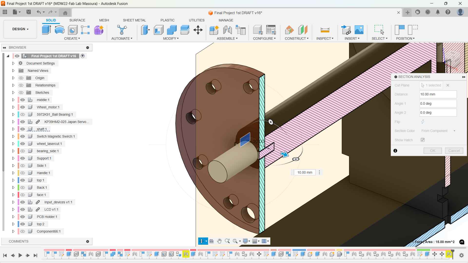
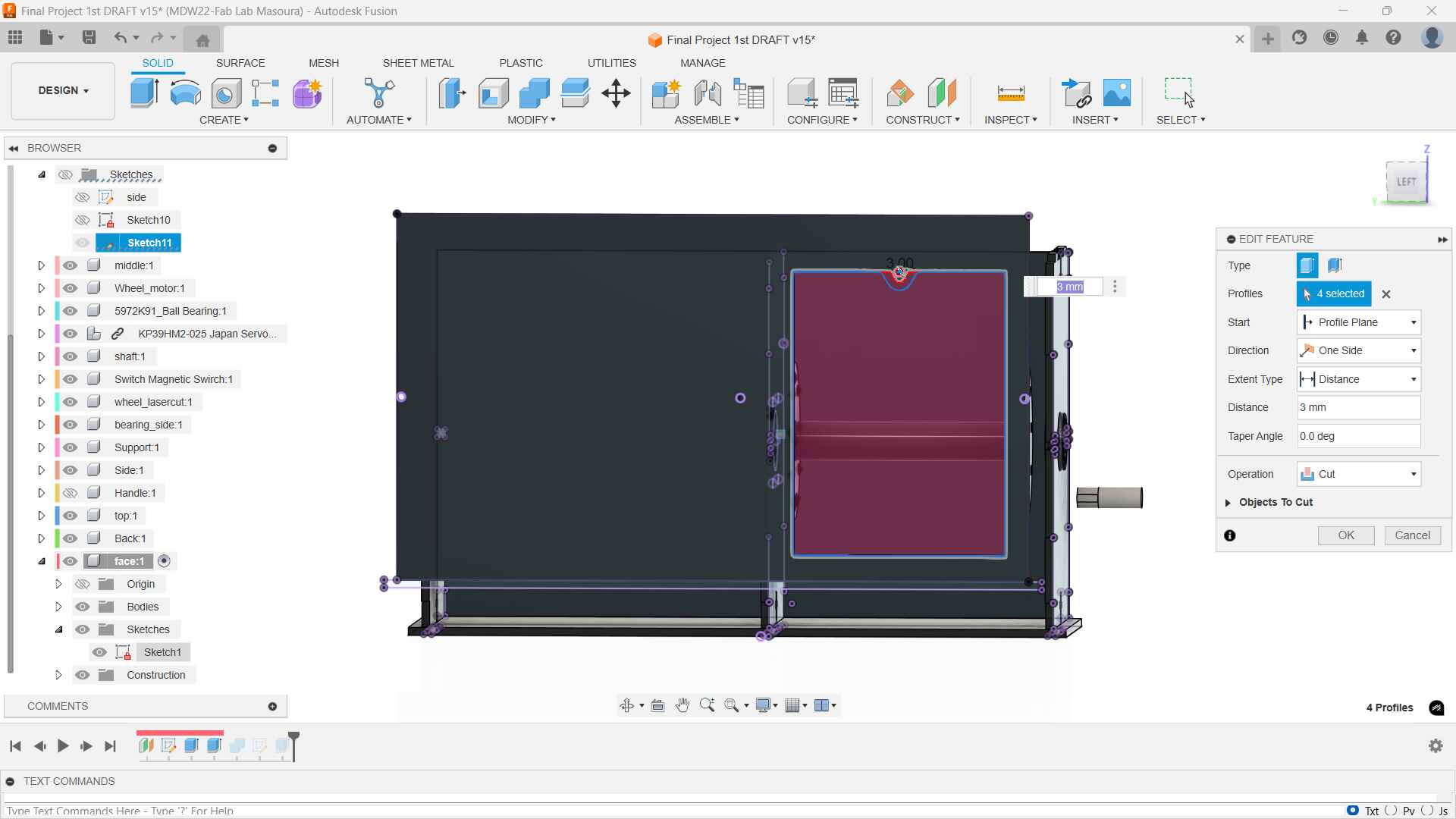
I extrude-cut the same opening in the shaft with 4mm. the support's configuration in the middle is extruded with 7mm in length to be secured in both the shaft and the laser cut wheel.
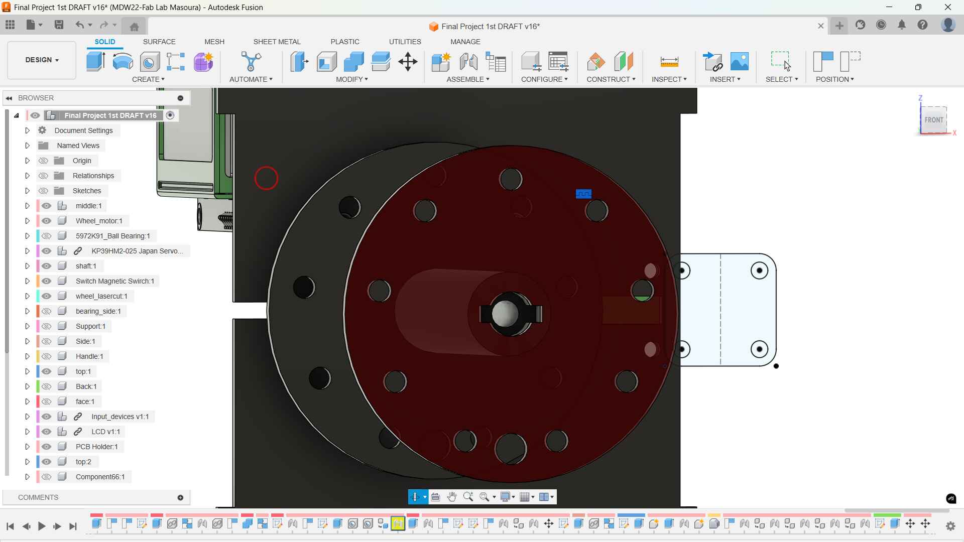
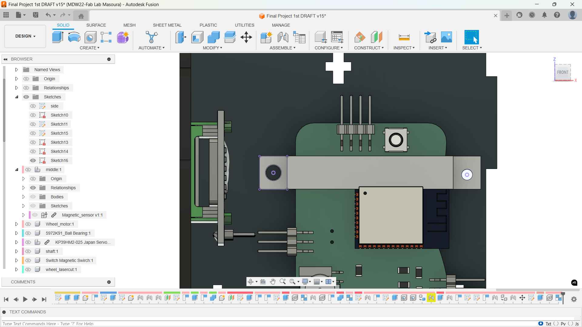
Section Analysis!
To help visualize the relationship betterI made a little section Analysis
-
Top and Bottom
Then I created the top and bottom parts. I sketched the top part and then extruded it. I added two 5mm holes for the capacitive touch buttons.
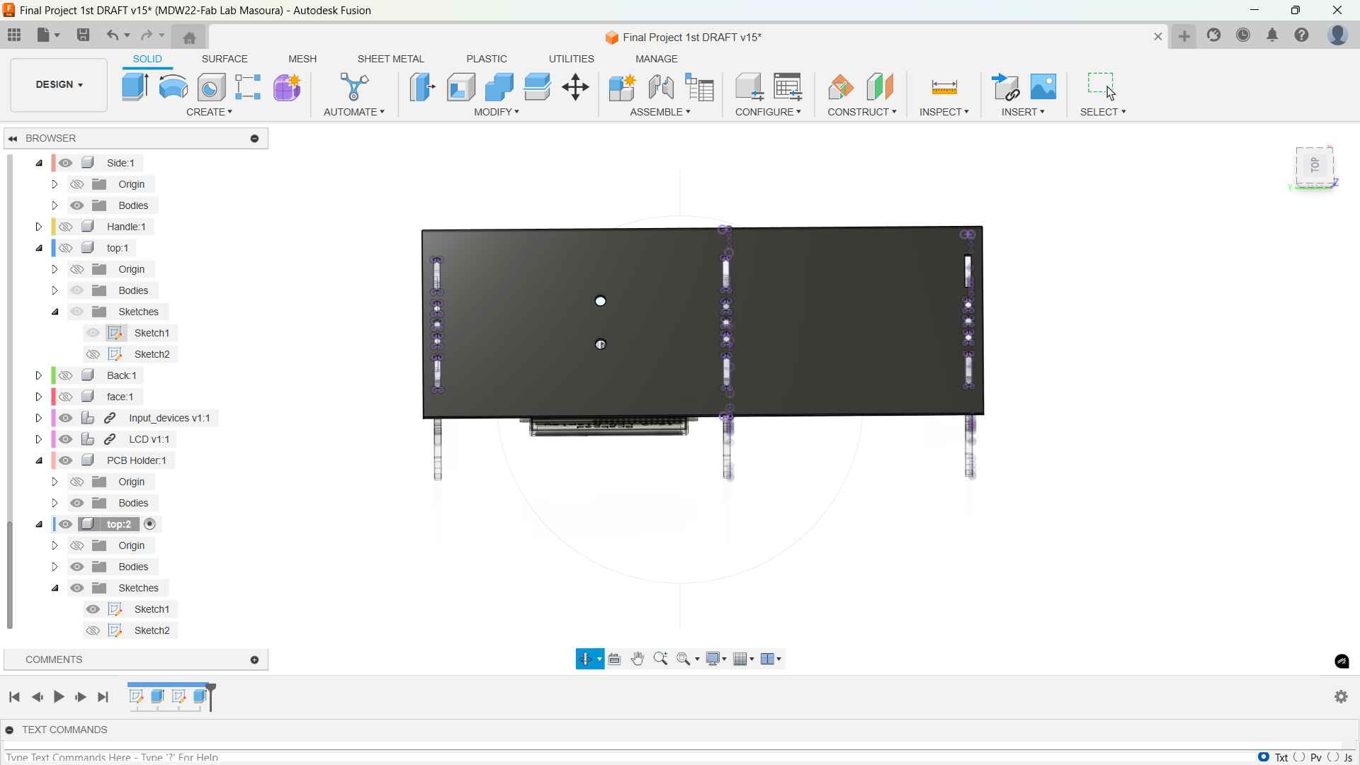
Front and Back
After placing the top and bottom in position I created a sketch that projected the sides and created constrians. Then I extruded it and sketched over it some kind of stopper and a extrude ccutted the opening so the cards could be visible.
I also added a small tip to the front side to hold the cards in place and to make it look aesthetically pleasing.
The back is plain except for a DC Jack opening
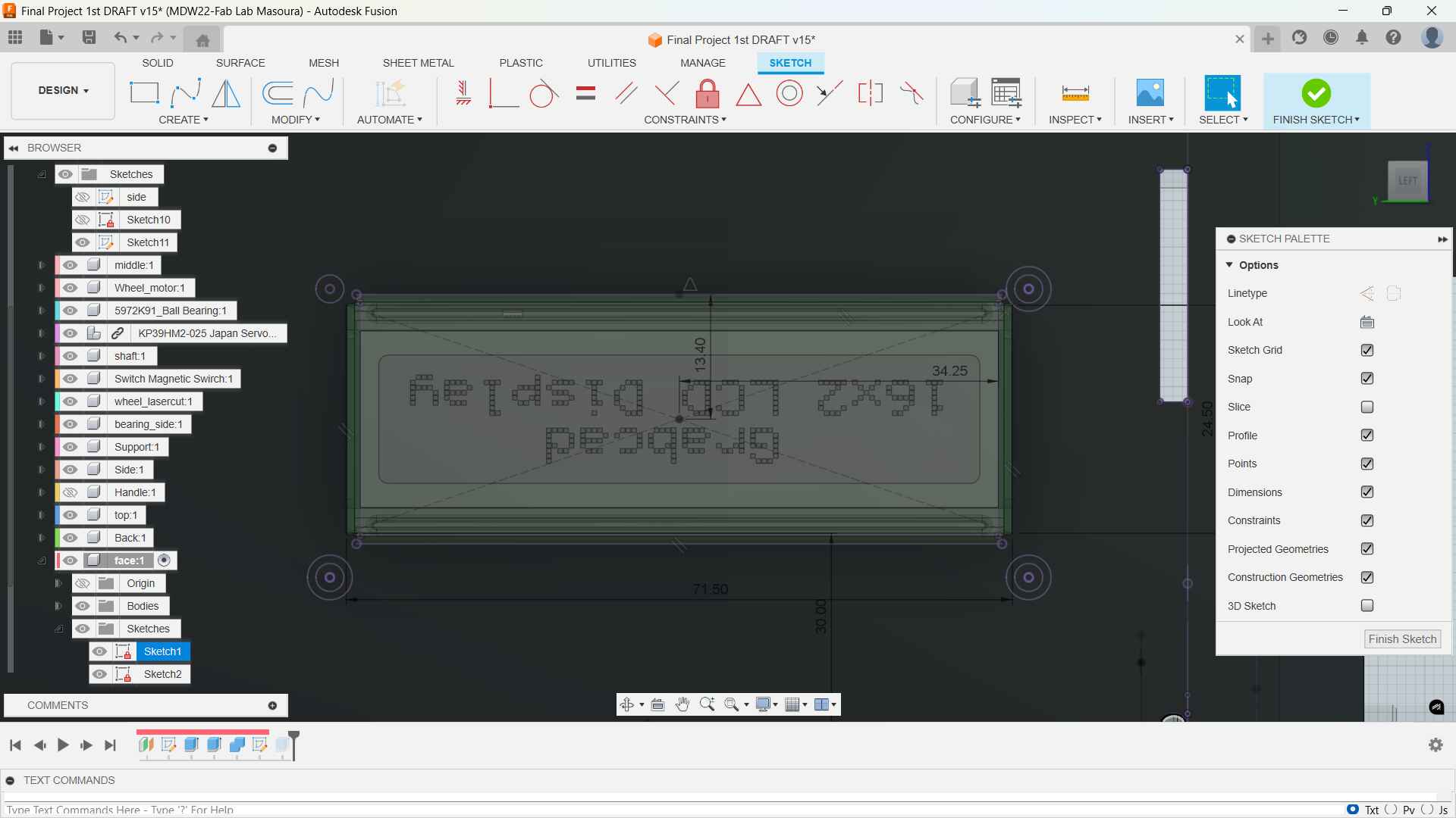
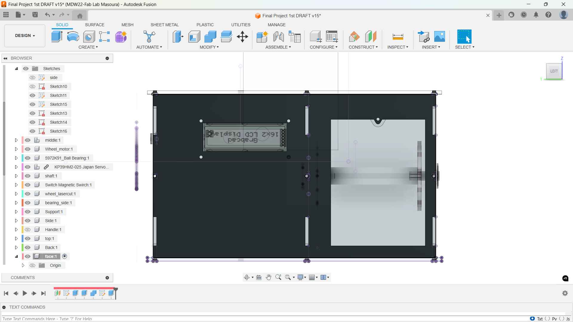
I import an LCD I2C from GrabCAD and prpojected its holes and opening to fit in then I extrude cut it.
Stickers
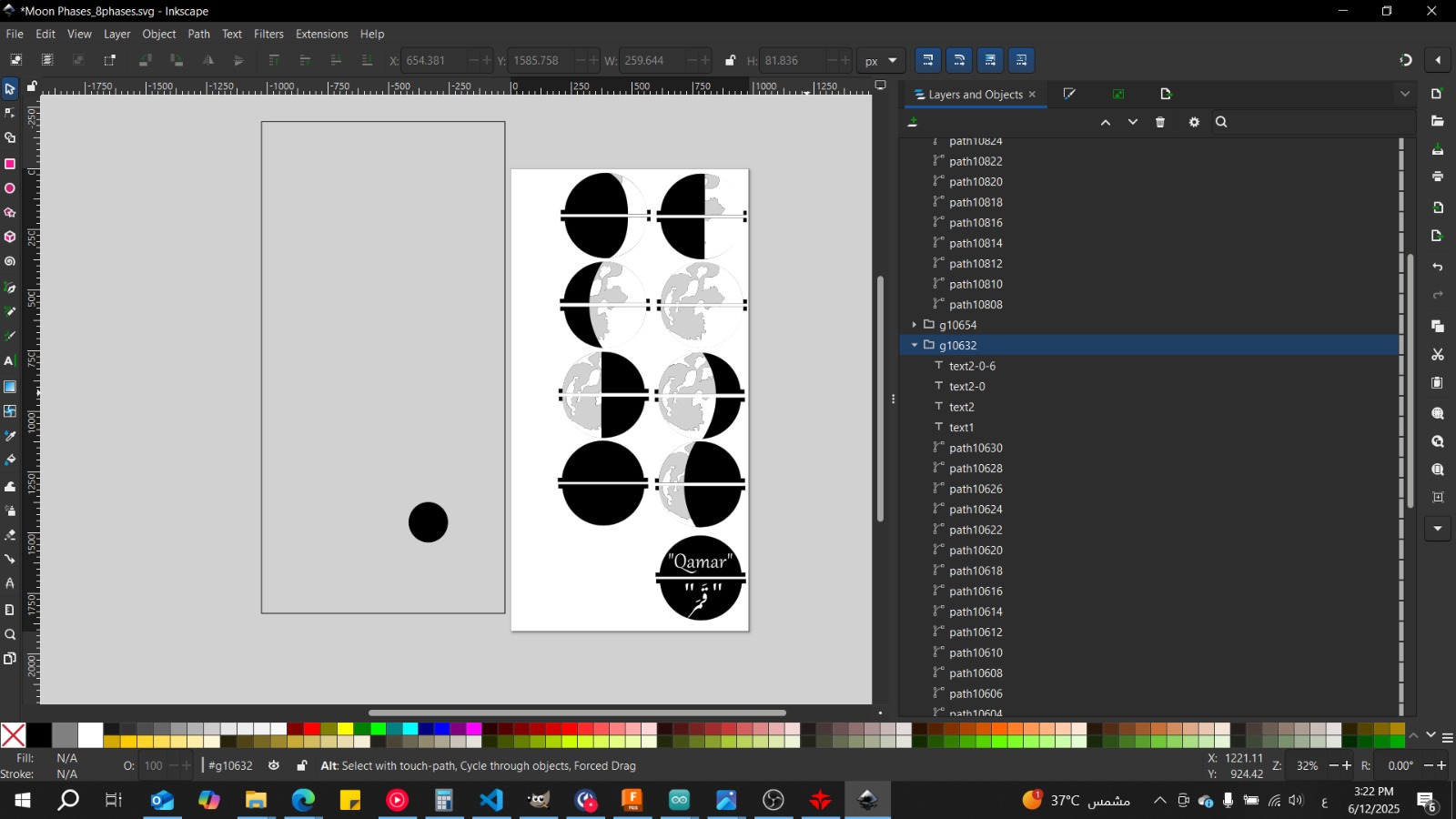
For the stickers I used the phases Simone Grietz provided in her flip moon here's the link to her flip moon.
I asked Doaa's help in making the stickers so we can print it wit our printer on ssticker paper and god
please her heart she did.
Fabrication
Laser Cutting

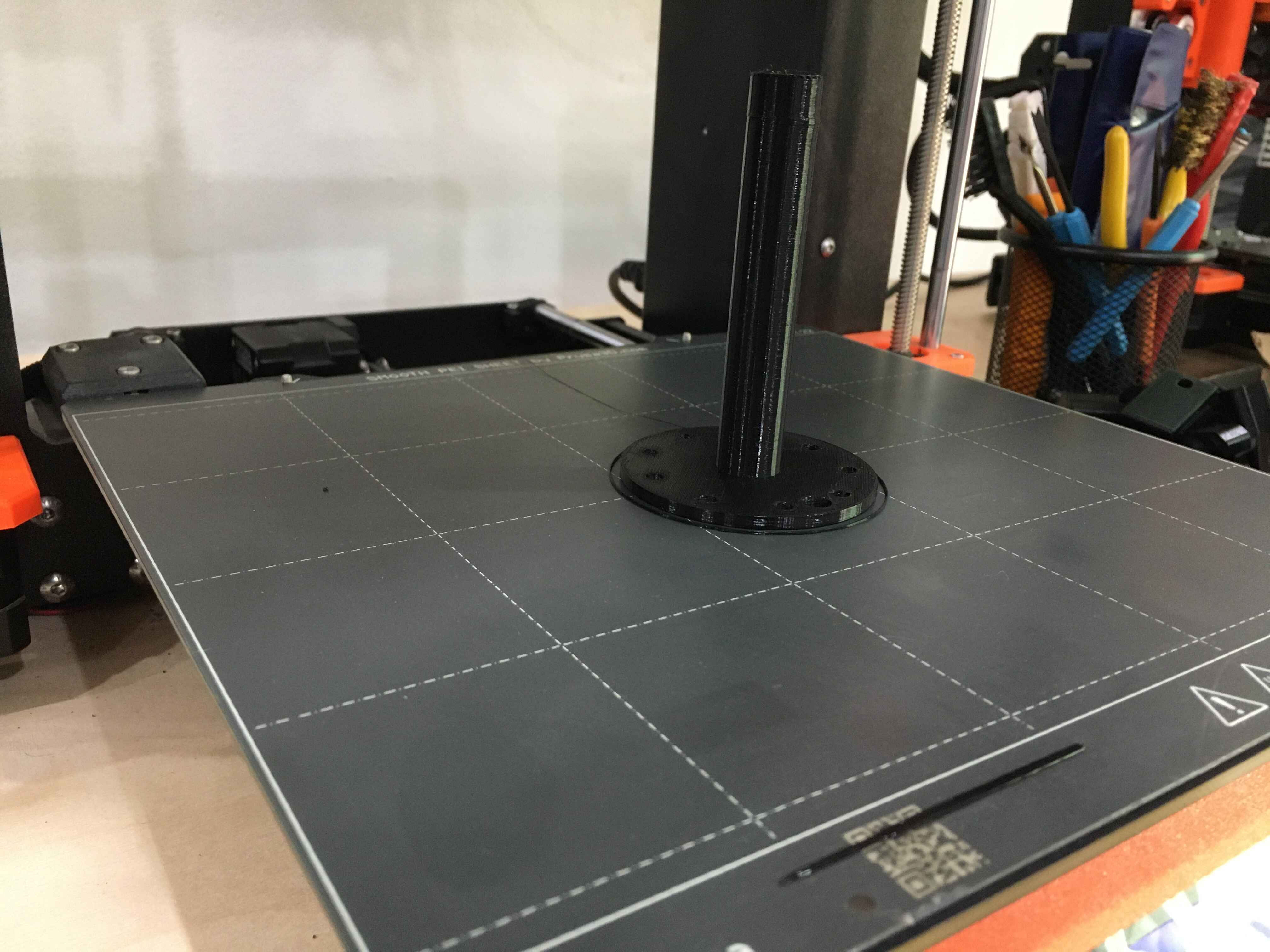
3D Printing
sticker prinitng
.jpg)
PCB Design & Fabrication
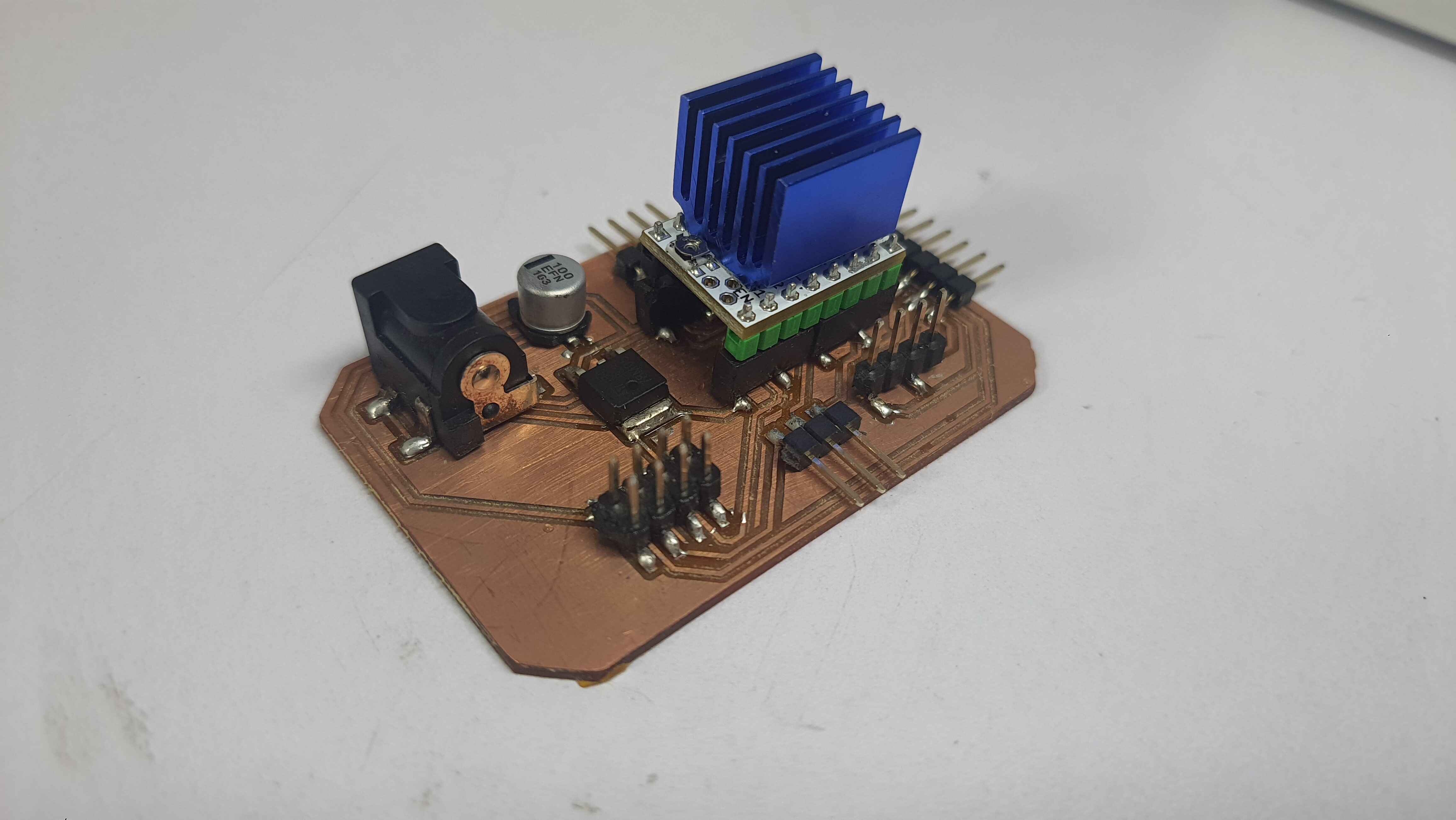
I decided early on that I'll be using the controller pcb I used in Input devices Week. I wanted to design an extension board for the stepper motor and the TMC stepper driver plus the LCD.
Iwill be using the same fabrication processes I tried in Electronics Production Week .
Stepper PCB
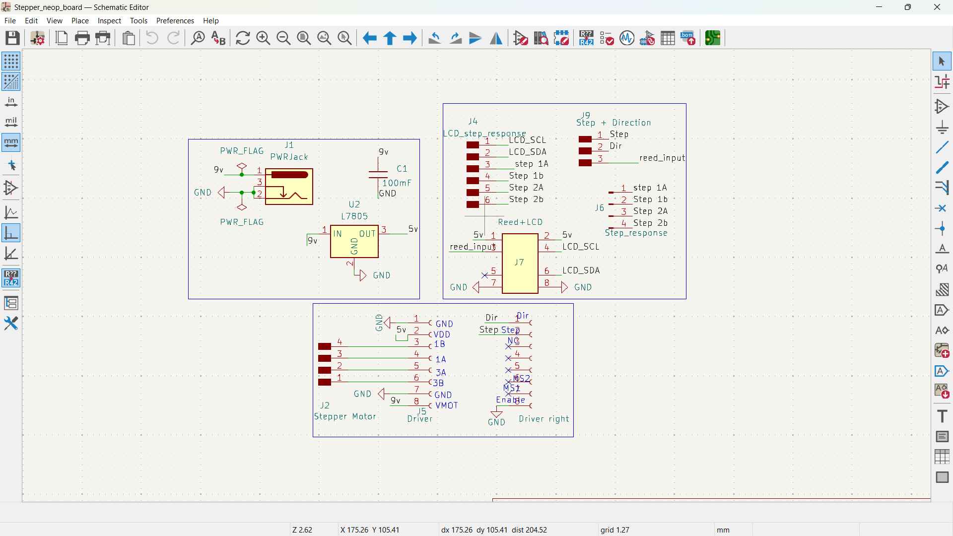
Here's the schematic for the board
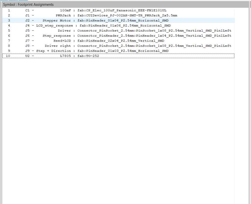
Here's the footprints for the board
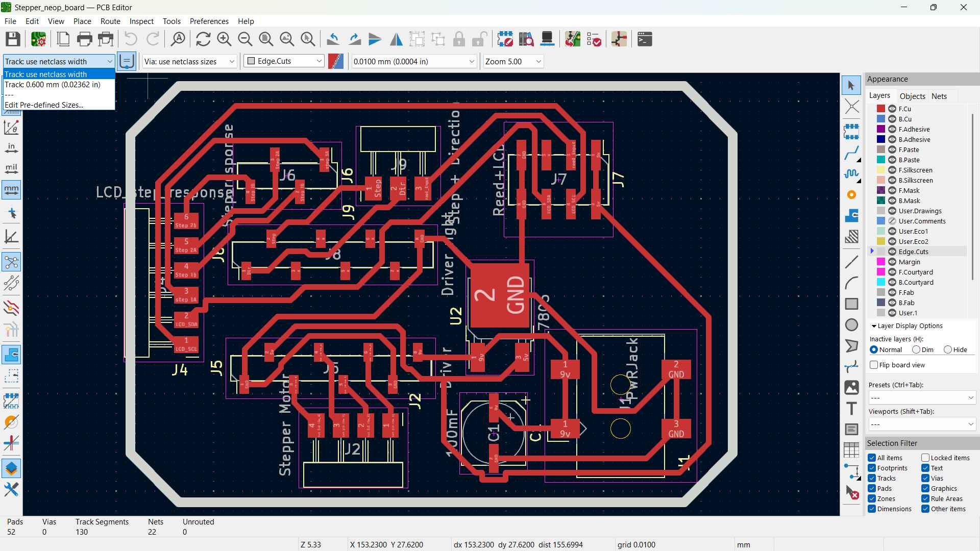
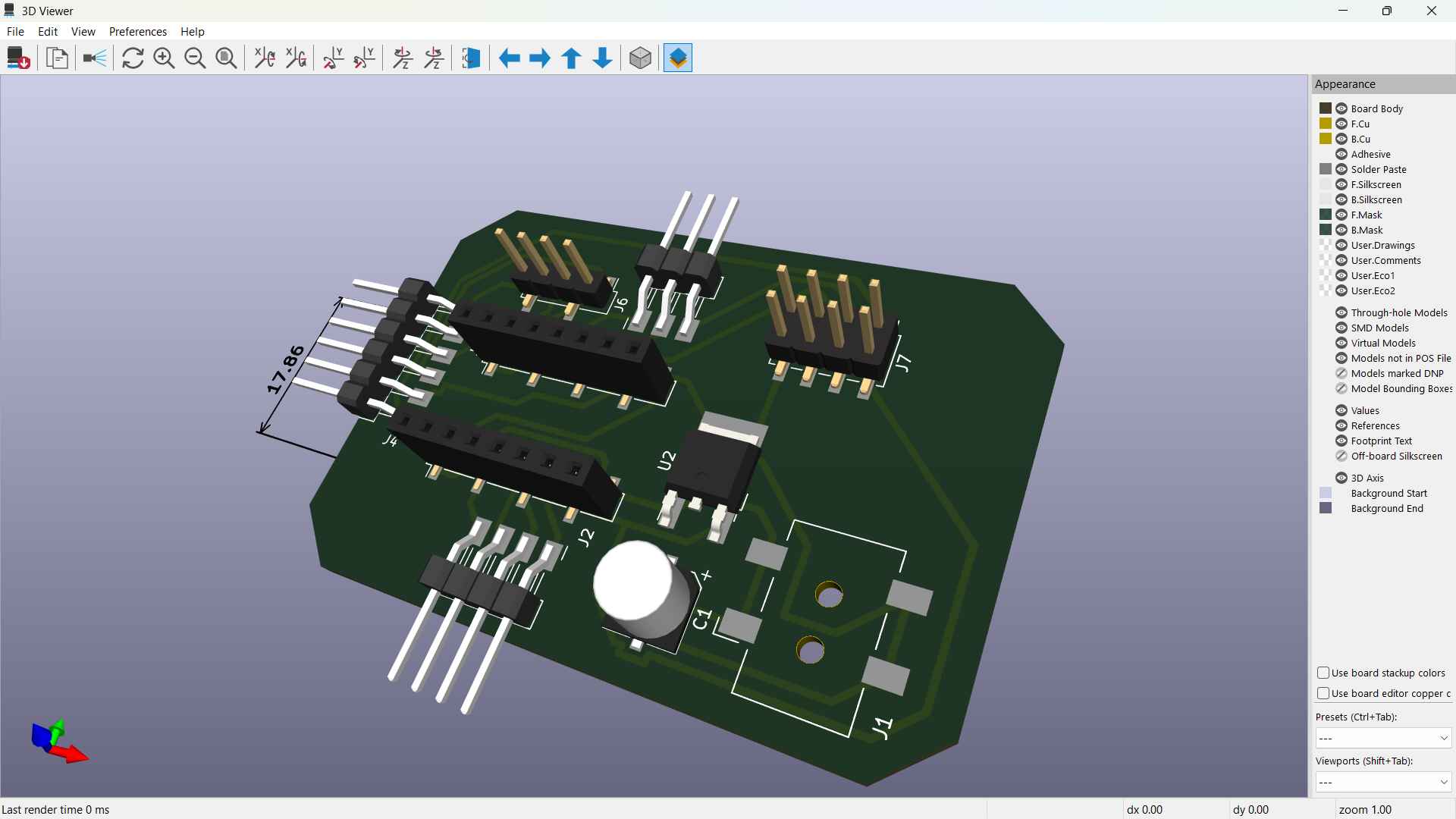
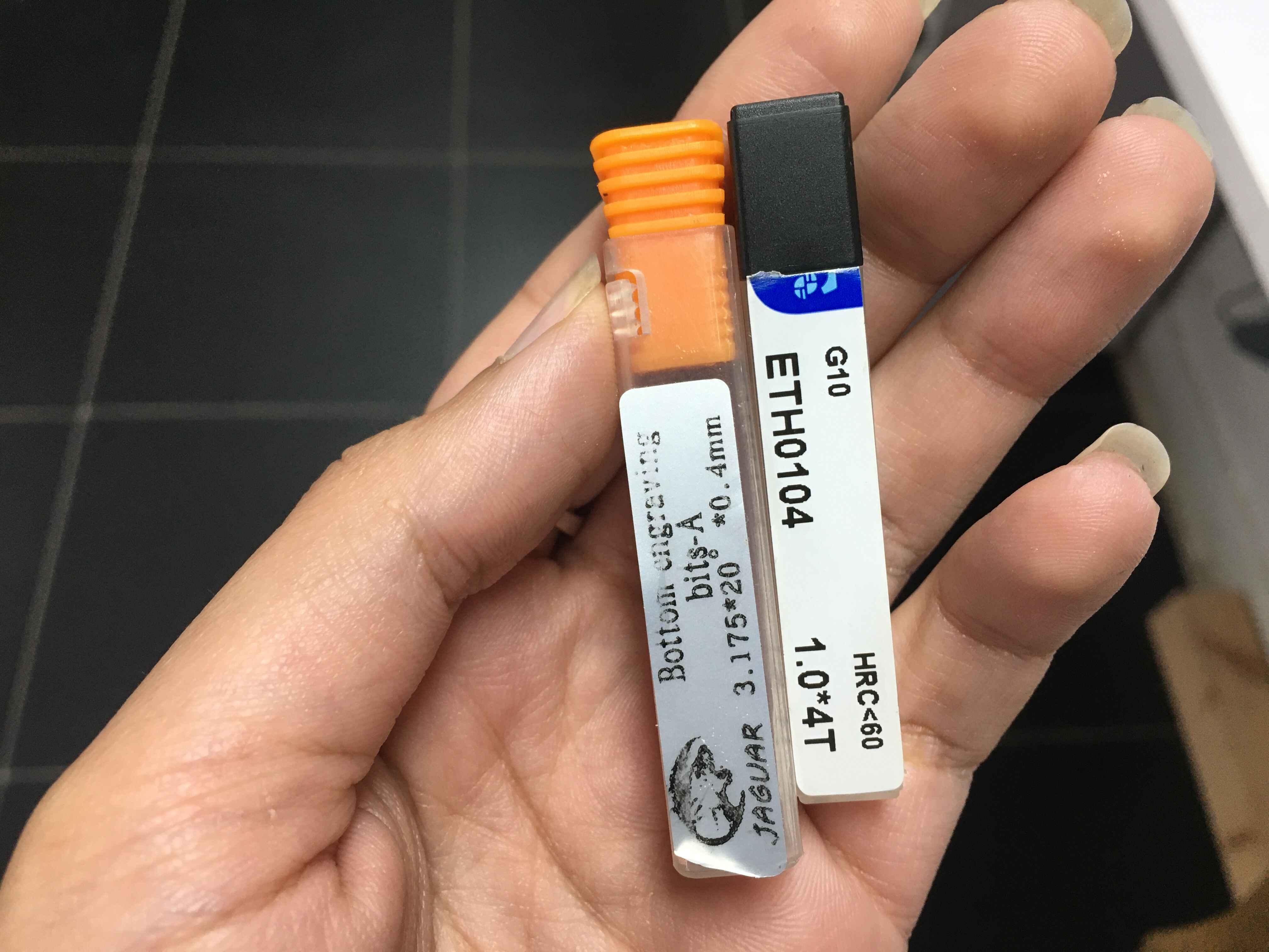
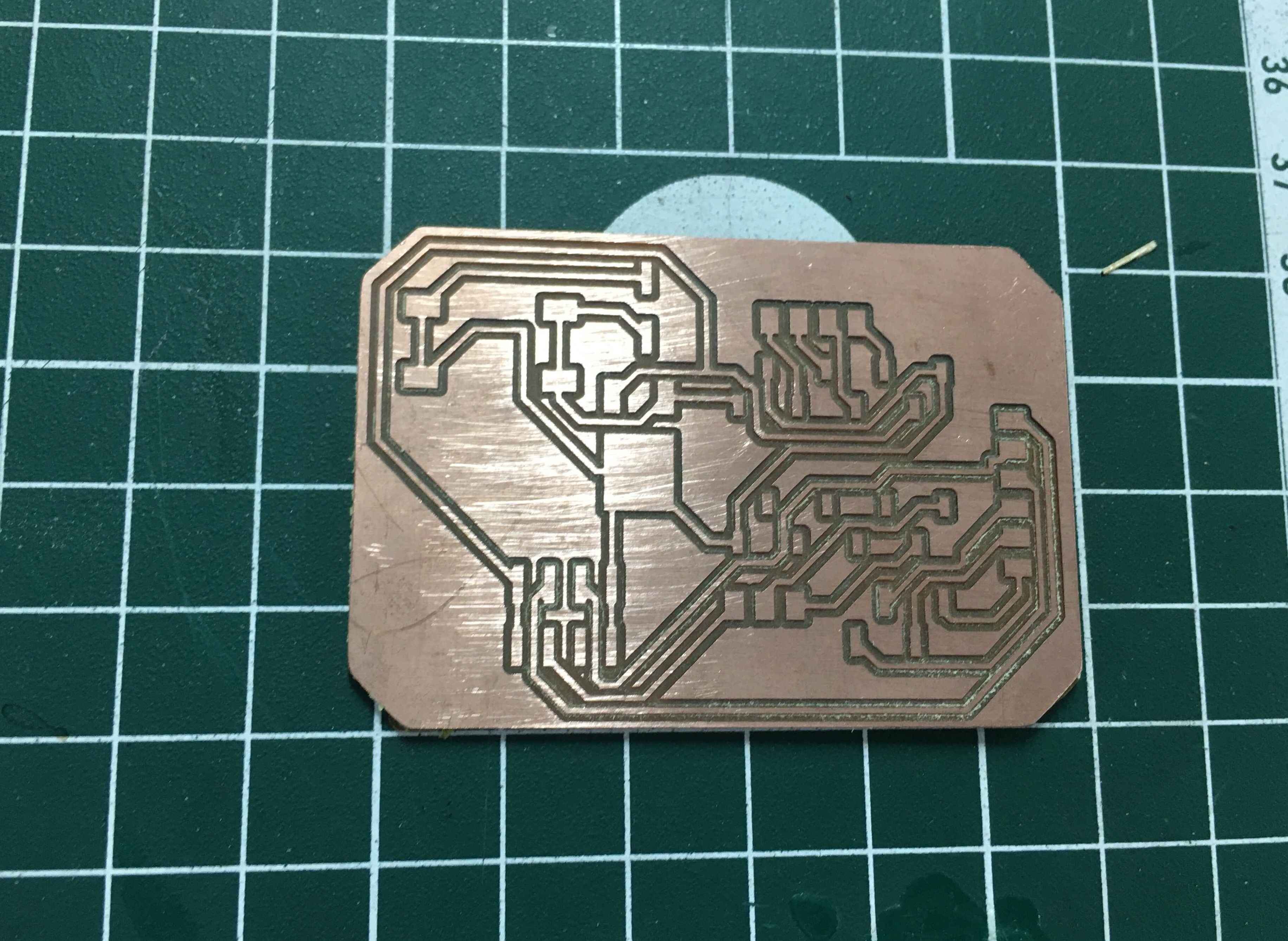
Here's the final design with a traces of 0.6mm in width because I'm now traumatized.
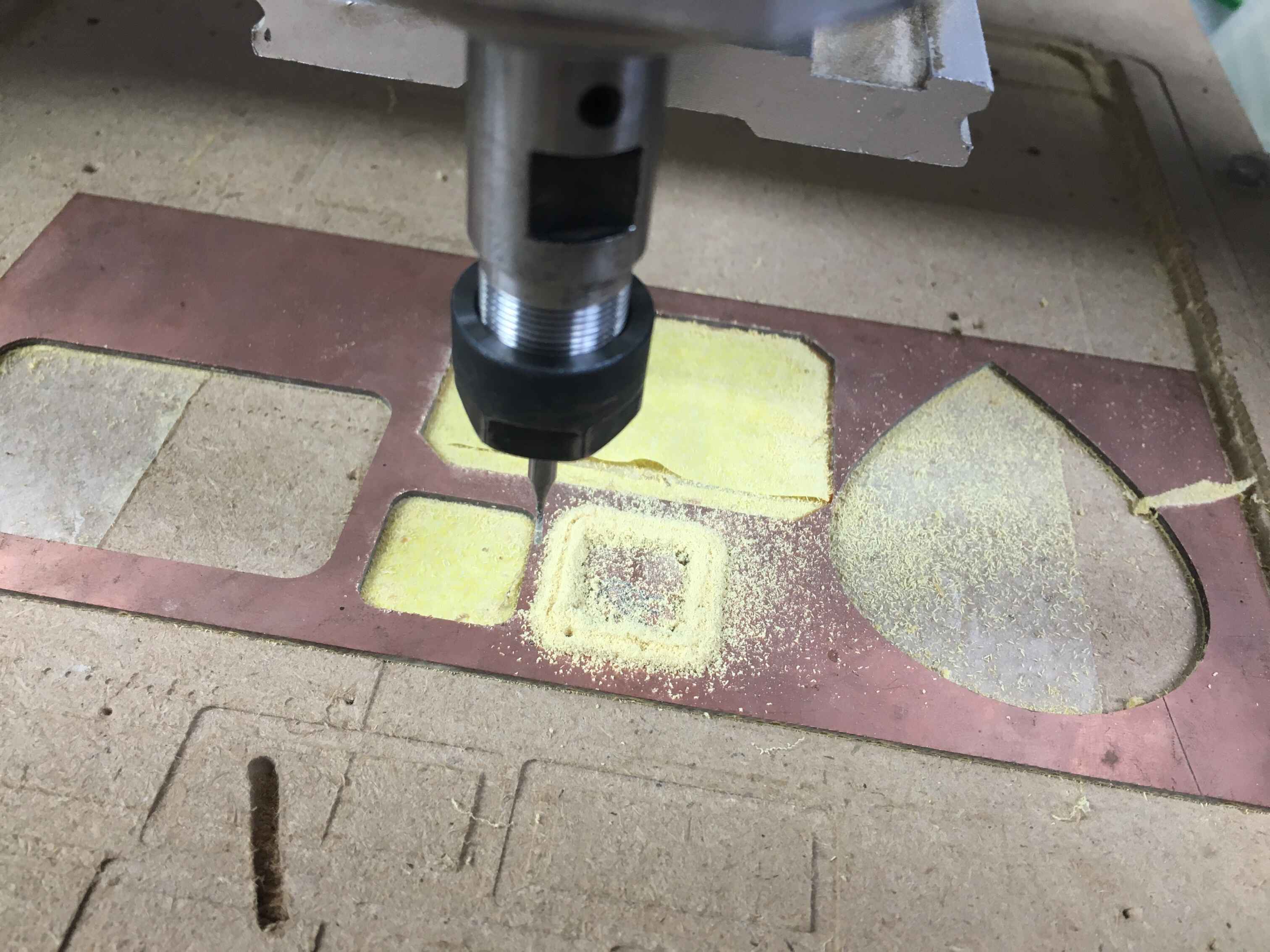
PCB Fabrication
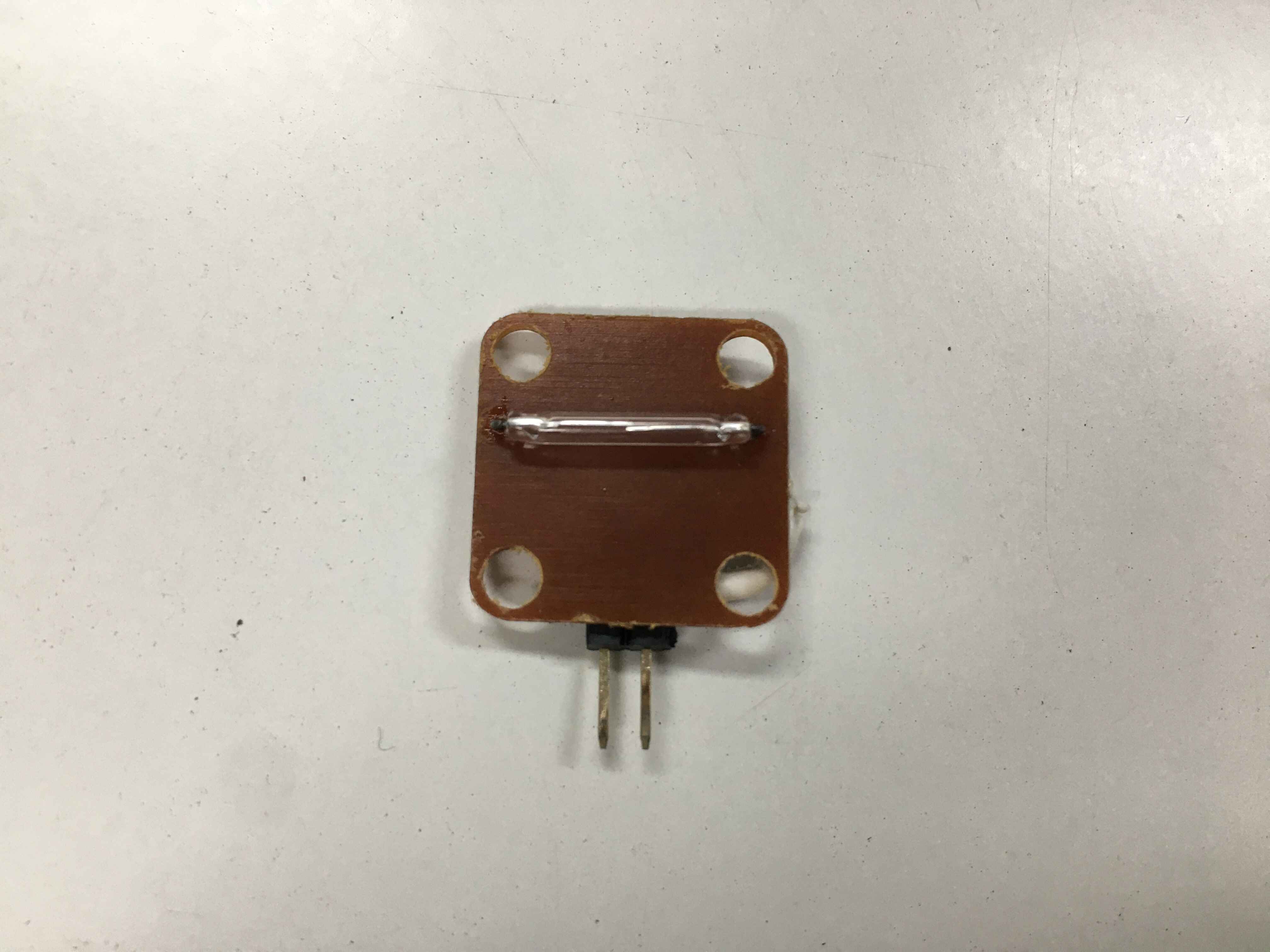
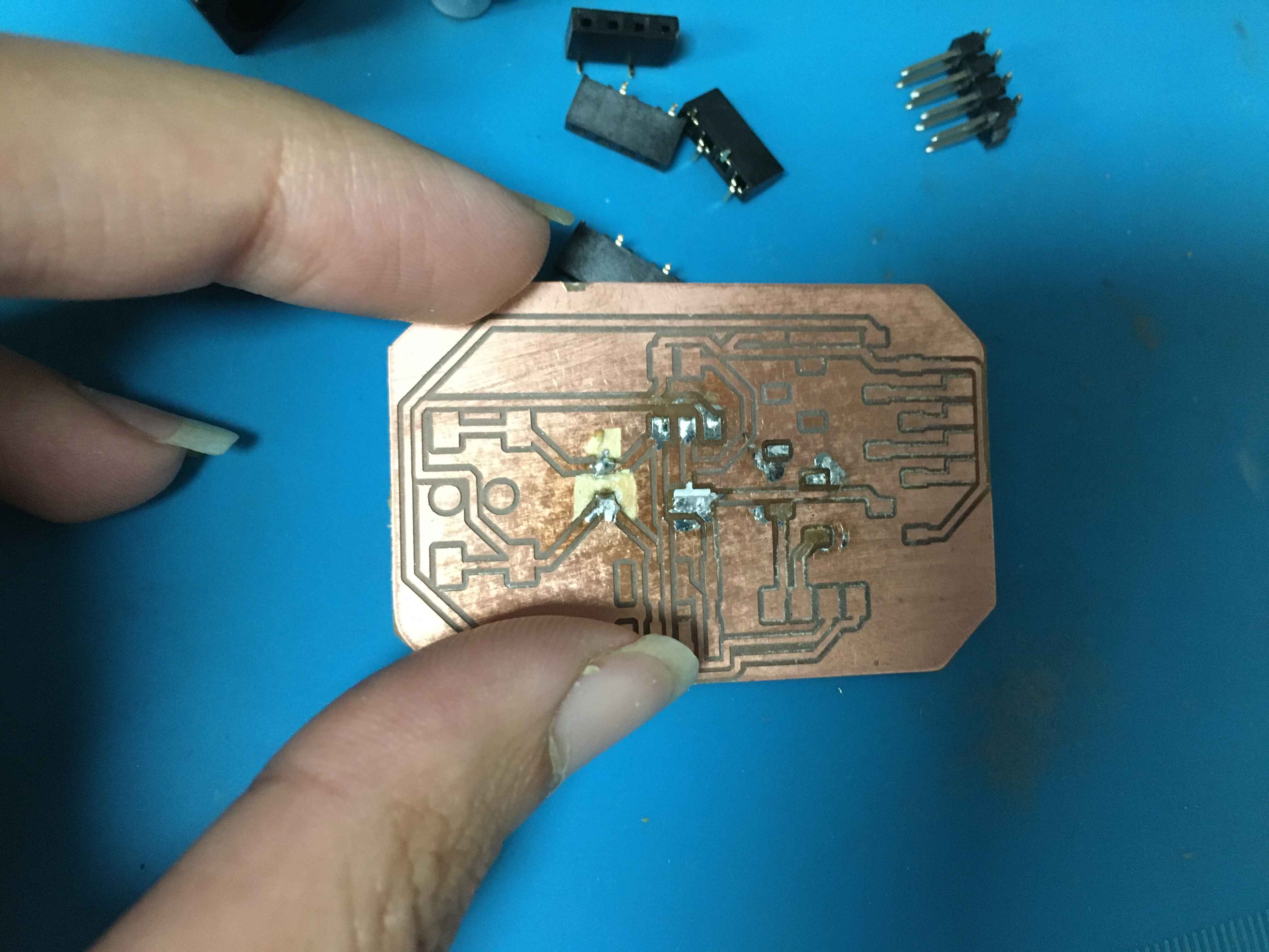
Reed PCB
I wanted to make my own input device that will act as the homing sensor for the magnet I put in the shaft so I decided since we didn't have any hall effect sensors I'll use the reed sensor. It senses the presence of magnets nearby. I didn't add a pull_up resistor since I can add that in the ESp32 code.
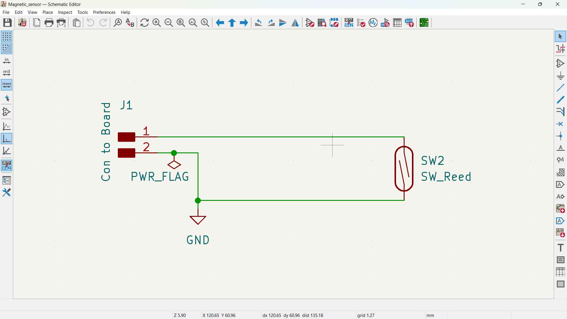
Here's the schematic for the board
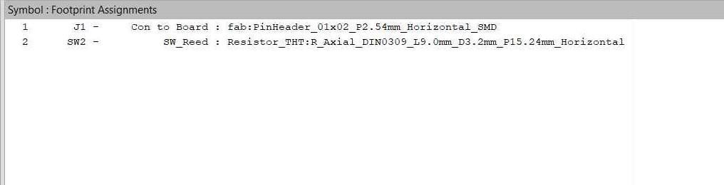
Here's the footprints for the board
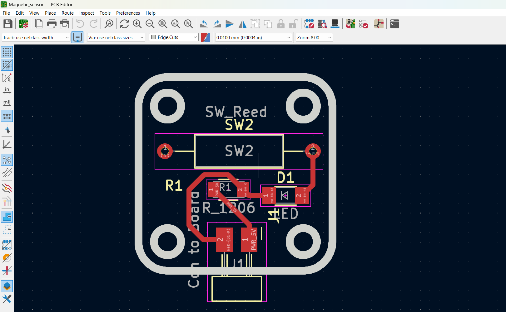
Here's the final design with a traces of 0.6mm in width.
Soldering
Electronics
API
In the embedded programming week I tried retrieving the Data from NASA API. I wanted to parse the data but unfortunately didn't have the time. but now I tried both retrieving the data and parsing it.
Request from API
First thing I started by getting The moon data from FarmSense API which sends a lot of lunar data for example: phase name, illumination, moon's distance & AngularDiameter, etc..
This API uses UNIX Epoch in the API request which means I need means I need to turn the date to unix every time I want to retrieve the data for a certain date. Like here: https://api.farmsense.net/v1/moonphases/?d=1747403074 the number besides the id refers to a date, In the code this number is stored in a variable called targetData. So this has to be done manually in the code and I used a Unix-Epoch Timestamp Converter.
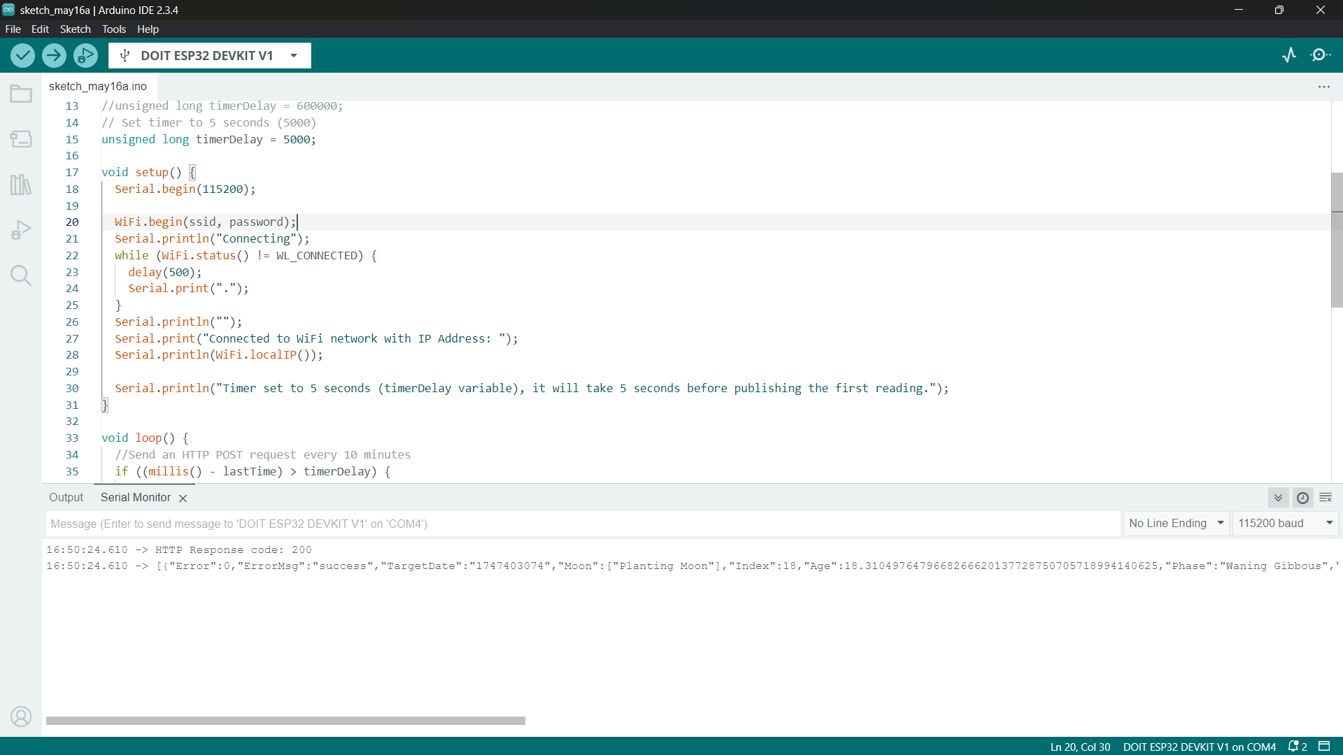
For my project I only need one data which is the phase name. At first I thought I need illumination but nope this is not helpful since it's only telling how much is the moon shining not the actual phase. For now I'm just printing all the returned data on the serial, maker sure it doesn't run any problems like error or wifi connection problems or gibberish data and make some parsing of the returned JSON file to print each returned value in its variable: "Index, Age, Phase, Distance, Illumination, AngularDiameter, SunAngularDiameter, DistanceToSun" . This code also sends a request every 10 seconds which will bombard your serial I recommend increasing the time.
 #include WiFi.h>
#include HTTPClient.h>
#include ArduinoJson.h>


const char* ssid = "";
const char* password = "";

const char* HorizonServer = "https://api.farmsense.net/v1/moonphases/?d=1747403074";
unsigned long lastTime = 0;
// Timer set to 10 minutes (600000)
unsigned long timerDelay = 600000;

void setup() {
  Serial.begin(115200);


  JsonDocument doc;

  DeserializationError error = deserializeJson(doc, input);

  if (error) {
    Serial.print("deserializeJson() failed: ");
    Serial.println(error.c_str());
    return;
  }

  JsonObject root_0 = doc[0];
  int root_0_Error = root_0["Error"];
  const char* root_0_ErrorMsg = root_0["ErrorMsg"];
  const char* root_0_TargetDate = root_0["TargetDate"];

  const char* root_0_Moon_0 = root_0["Moon"][0];  //

  int root_0_Index = root_0["Index"];
  double root_0_Age = root_0["Age"];
  const char* root_0_Phase = root_0["Phase"];
  double root_0_Distance = root_0["Distance"];
  float root_0_Illumination = root_0["Illumination"];
  double root_0_AngularDiameter = root_0["AngularDiameter"];
  double root_0_DistanceToSun = root_0["DistanceToSun"];
  double root_0_SunAngularDiameter = root_0["SunAngularDiameter"];


  WiFi.begin(ssid, password);
  Serial.println("Connecting");
  while (WiFi.status() != WL_CONNECTED) {
    delay(500);
    Serial.print(".");
  }
  Serial.println("");
  Serial.print("Connected to WiFi network with IP Address: ");
  Serial.println(WiFi.localIP());

  Serial.println("Timer set to 5 seconds (timerDelay variable), it will take 5 seconds before publishing the first reading.");
}

void loop() {
  //Send an HTTP POST request every 10 minutes
  if ((millis() - lastTime) > timerDelay) {
    //Check WiFi connection status
    if (WiFi.status() == WL_CONNECTED) {
      HTTPClient http;

      String serverPath = HorizonServer;

      http.begin(serverPath.c_str());


      int httpResponseCode = http.GET();

      if (httpResponseCode > 0) {
        Serial.print("HTTP Response code: ");
        Serial.println(httpResponseCode);
        String payload = http.getString();
        Serial.println(payload);
      } else {
        Serial.print("Error code: ");
        Serial.println(httpResponseCode);
      }
      // Free resources
      http.end();
    } else {
      Serial.println("WiFi Disconnected");
    }
    lastTime = millis();
  }
}
Output Devices
-
Stepper Motor + TMC 2208
First I tested the stepper with the A4908 steeper driver until we purchase the TMC drivers for me and Amr. I uploaded a test code from here. Then I went ahead and integrated the API. Then Once that was done I moved to parsing the data along with moving the motor only when it reads an illumination is bigger than 16 which was while I was testing. The illunination was around 18.
Once we got the TMC and I printed the shaft to test the movement and fabricated the pcb. I uploaded the same code. It was a lot smoother and quiter.
-
LCD
NTP and phase on LCD Testing
I tested connecting to the NTP server and displaying the date. I used this code. And it displayed the date while updating it every second.
>First trial was adding a neopixel to indicate the wifi connection and the movement happens once the neopixel tuns red. Here I didn't play with the Reed sensor yet. so It doesn't home yet. at the beginning I wanted to add a Neopixel but ended up abandoning the idea for reasons I will mention later. I used ChatGPT's help in creating the parsing of the data with ArduinoJSON libtary.
#include WiFi.h>
#include HTTPClient.h>
#include ArduinoJson.h>
const char* ssid = " ";
const char* password = "";
int directionPin = 22;
int stepsPin = 21;
const char* HorizonServer = "https://api.farmsense.net/v1/moonphases/?d=1747403074";
unsigned long lastTime = 0;
unsigned long timerDelay = 60000;
int Led = 13;
int buttonpin = 23;
void setup() {
Serial.begin(115200);
NeoPixel.begin();
pinMode(Led, OUTPUT);
pinMode(buttonpin, INPUT);
pinMode(directionPin, OUTPUT);
pinMode(stepsPin, OUTPUT);
WiFi.begin(ssid, password);
Serial.println("Connecting to WiFi...");
for (int pixel = 0; pixel < NUM_PIXELS; pixel++) {
NeoPixel.setPixelColor(pixel, NeoPixel.Color(155, 0, 155));
NeoPixel.show();
delay(1000);
}
while (WiFi.status() != WL_CONNECTED) {
delay(500);
Serial.print(".");
}
Serial.println("\nConnected to WiFi!");
}
void loop() {
if ((millis() - lastTime) > timerDelay || lastTime == 0) {
if (WiFi.status() == WL_CONNECTED) {
HTTPClient http;
http.begin(HorizonServer);
int httpResponseCode = http.GET();
if (httpResponseCode == 200) {
String Moon_data = http.getString();
Serial.println("Response:");
Serial.println(Moon_data);
// Use ArduinoJson to parse it
StaticJsonDocument 2048> doc;
DeserializationError error = deserializeJson(doc, Moon_data);
if (error) {
Serial.print("deserializeJson() failed: ");
Serial.println(error.c_str());
return;
}
JsonObject root_0 = doc[0];
int errorCode = root_0["Error"];
const char* phase = root_0["Phase"];
double age = root_0["Age"];
float illumination = root_0["Illumination"];
Serial.println("--- Parsed Data ---");
Serial.print("Phase: ");
Serial.println(phase);
Serial.print("Age: ");
Serial.println(age);
Serial.print("Illumination: ");
Serial.println(illumination);
//-------------------Motor--------
//Homingggg
int val = digitalRead(buttonpin); // read and assign the value of digital interface 3 to val
Serial.println(val);
if (val == 0)
{
digitalWrite(Led, HIGH);
digitalWrite(stepsPin, LOW);
digitalWrite(directionPin, LOW); // Enables the motor to move in a particular direction
Serial.println("Motor stopped");
} else if (val == 1) {
digitalWrite(directionPin, HIGH);
if (age >= 16) {
for (int pixel = 0; pixel < NUM_PIXELS; pixel++) {
NeoPixel.setPixelColor(pixel, NeoPixel.Color(150, 0, 0));
}
NeoPixel.show(); // update to the NeoPixel Led Strip
delay(1000); // 1 second on time
for (int x = 0; x < 200; x++) {
digitalWrite(stepsPin, HIGH);
delayMicroseconds(500);
digitalWrite(stepsPin, LOW);
delayMicroseconds(500);
Serial.println("Motor moving");
}
}
}
delay(1000);
} else {
Serial.print("HTTP Error code: ");
Serial.println(httpResponseCode);
}
http.end();
} else {
Serial.println("WiFi Disconnected");
}
lastTime = millis();
}
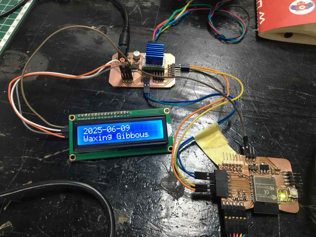
} Second I trial I integrated the LCD and removed the neopixel. I tried printing the both the phase and date on the LCD.
 #include WiFi.h>
#include WiFiClientSecure.h>
#include HTTPClient.h>
#include LiquidCrystal_I2C.h>
#include ArduinoJson.h>
#include time.h>
#define stepPin 18
#define dirPin 19

int reed_switch = 26;
bool val;
/////-Arrows for time
int next_day;
int prevday;
int dayoffset = 0;
// Serial.print("Touch0 value is = ");
// Serial.print(touch_sensor_value);
// Serial.print("   Touch7 value is = ");
// Serial.println(touch_sensor2_value);
// delay(200);
const char* ssid = "San3a Tech Network";
const char* password = "WeLoveSan3aNetwork";

static const long GMT_OFFSET_SEC = 2 * 3600;
static const int DAYLIGHT_OFFSET_SEC = 0;

const char* ntpServer1 = "pool.ntp.org";
const char* ntpServer2 = "time.nist.gov";

LiquidCrystal_I2C lcd(0x27, 16, 2);
void homing() {
  Serial.println("Homing...");
  digitalWrite(dirPin, HIGH);

  // Step until the switch goes LOW
  while (digitalRead(reed_switch) == HIGH) {
    digitalWrite(stepPin, HIGH);
    delayMicroseconds(700);
    digitalWrite(stepPin, LOW);
    delayMicroseconds(700);
  }

  Serial.println("Home position reached");

  for (int i = 0; i < 20; i++) {  // ~20 microsteps back
    digitalWrite(dirPin, HIGH);   // opposite direction
    digitalWrite(stepPin, HIGH);
    delayMicroseconds(700);
    digitalWrite(stepPin, LOW);
    delayMicroseconds(700);
  }
}


void connectWiFi() {
  WiFi.mode(WIFI_STA);
  WiFi.begin(ssid, password);
  Serial.print("Wi-Fi: ");
  while (WiFi.status() != WL_CONNECTED) {
    Serial.print(".");
    delay(500);
  }
  Serial.println(" connected");
  lcd.clear();
  lcd.setCursor(0, 0);
  lcd.print("Wifi Conntected");
}

void syncTime() {
  configTime(GMT_OFFSET_SEC, DAYLIGHT_OFFSET_SEC, ntpServer1, ntpServer2);
  struct tm tm;
  while (!getLocalTime(&tm)) {
    Serial.println("Waiting for NTP …");
    delay(1000);
  }
  Serial.println("Time synced");
}

String fetchMoonPhaseAndIllumination(time_t utcEpoch, int& illumValue) {
  // FarmSense
  String url = "https://api.farmsense.net/v1/moonphases/?d=" + String(utcEpoch);
  Serial.println("GET " + url);

  WiFiClientSecure client;
  client.setInsecure();
  HTTPClient http;
  if (!http.begin(client, url)) return "HTTP begin failed";

  int code = http.GET();
  if (code != HTTP_CODE_OK) {
    http.end();
    return "HTTP err " + String(code);
  }

  DynamicJsonDocument doc(1024);
  DeserializationError err = deserializeJson(doc, http.getString());
  http.end();
  if (err) return "JSON err";

  // Extract the phase name and illumination
  if (!doc[0].containsKey("Phase") || !doc[0].containsKey("Illumination")) return "No field";

  float illumFloat = doc[0]["Illumination"].as String>().toFloat();
  illumValue = lroundf(illumFloat * 100);
  return doc[0]["Phase"].as String>();
}

void showOnLCD(const char* dateStr, const String& phase) {
  lcd.clear();
  lcd.setCursor(0, 0);
  lcd.print(dateStr);
  lcd.setCursor(0, 1);
  lcd.print(phase);
}

void setup() {
  Serial.begin(115200);
  delay(200);
  pinMode(reed_switch, INPUT_PULLUP);
  pinMode(stepPin, OUTPUT);
  pinMode(dirPin, OUTPUT);
  lcd.init();
  lcd.backlight();
  homing();
  connectWiFi();
  syncTime();
}

void loop() {
  static unsigned long lastQuery = 0;
  const unsigned long QUERY_INTERVAL = 60UL * 60UL * 1000UL;  // 1 h
  next_day = touchRead(T0);
  prevday = touchRead(T7);
  if (millis() - lastQuery > QUERY_INTERVAL || lastQuery == 0) {
    lastQuery = millis();

    time_t utcNow = time(nullptr);
    int illumInt = 0;

    String phase = fetchMoonPhaseAndIllumination(utcNow, illumInt);

    struct tm localTm;
    localtime_r(&utcNow, &localTm);
    char dateBuf[17];
    strftime(dateBuf, sizeof(dateBuf), "%Y-%m-%d", &localTm);

    showOnLCD(dateBuf, phase);
    Serial.printf("%s | %s | illum %d\n", dateBuf, phase.c_str(), illumInt);

    Serial.printf("Displayed %s | %s\n", dateBuf, phase.c_str());
  }

  // Tiny delay so loop isn’t 100 % busy
  delay(100);
}
Input Devices
Homing with Reed Magnetic Switch
Doaa used the reed before so I looked up her documentation as reference and tested her test code. At first for the testing phase I used the ready module before I made mine. I made a place for it in the design but had trouble making the reed read the magnet in its cureeent designed position so for testing I used a double table to secure it in place for now. I used a simple code that rotates the motor until the reed detects a magnet. Thiscode also prints on the serial if the motor is moving or stopped.
#define stepPin 18
#define dirPin 19

int buttonpin = 26;  //define magnetic ring sensor interface
bool val;             //define digital variable val

void setup() {
  Serial.begin(115200);
  pinMode(buttonpin, INPUT);
  pinMode(stepPin, OUTPUT);
  pinMode(dirPin, OUTPUT);
}
void loop() {
  val = digitalRead(buttonpin);
  if (val == LOW)
  {
    Serial.println("Motor Stopped");

    digitalWrite(stepPin, LOW);
    digitalWrite(dirPin, LOW);  /

  } else {

    digitalWrite(dirPin, LOW);
    for (int x = 0; x < 200; x++) {
      Serial.println("Motor Working");

      digitalWrite(stepPin, HIGH);
      delayMicroseconds(700);
      digitalWrite(stepPin, LOW);
      delayMicroseconds(700);
    }
    delay(1300);
  }
}
As you can see the 3mm acrylic was heavy on the motor and it kept heating up so much or making the shaft rotate backwards.
Playing with Time using the Capacitive Touch.
I wanted to add arrow that move the date up and down and tried capacitive touch before in my Input devices week but rather that FastCapcitve library I used the touch pins on the ESP32. I used this Code with my pcb and I used the same code and added the touch sensor library. I used the T0 and T7 pins to move the date up and down.
Final Code
I used ChatGPT to help me integrate the arrow and with the data parsing and breaking. I asked ChatGPT to generate a prompt that will create this full code for my project> Here's the prompts I generated:
Write Arduino code for an ESP32-based moon phase display device with the following features: Connects to Wi-Fi using given SSID and password. Syncs time using NTP (pool.ntp.org and time.nist.gov) and applies a +2 GMT offset. Fetches current moon phase using the FarmSense Moon API (https://api.farmsense.net/v1/moonphases/?d= + UTC timestamp). Parses the "Phase" field from the API JSON response. Displays the current date and moon phase on a 16x2 I2C LCD (0x27 address). Uses a stepper motor controlled via stepPin (GPIO 18) and dirPin (GPIO 19). Uses a reed switch (GPIO 26) for homing: motor rotates in one direction until reed switch is triggered, setting flap position to 0 ("welcome"). Maps moon phases to flap numbers (1–8): ini Copy Edit 0 = welcome sign 1 = New Moon 2 = Waxing Crescent 3 = First Quarter 4 = Waxing Gibbous 5 = Full Moon 6 = Waning Gibbous 7 = Last Quarter 8 = Waning Crescent Moves motor only in one direction (e.g., HIGH on dirPin) by calculating the difference between current and target flap. Supports 9 total flaps with 200 steps per flap. Implements capacitive touch input using ESP32 touch pins: T0 (touchRead) to advance the date T7 to go back in date Allows user to view moon phase on different days by offsetting the current UTC date with a dayOffset integer. Updates flap position and LCD when touch is detected or hourly. Keeps track of current flap to avoid unnecessary movement. Make sure: The motor does not move in reverse (always goes forward). The device re-homes correctly at startup using the reed switch. LCD updates cleanly with date and phase. The code includes debug Serial.println() statements to monitor actions. Use the LiquidCrystal_I2C, WiFi, HTTPClient, WiFiClientSecure, and ArduinoJson libraries..
  #include WiFi.h>
#include WiFiClientSecure.h>
#include HTTPClient.h>
#include LiquidCrystal_I2C.h>
#include ArduinoJson.h>
#include time.h>

#define stepPin 18
#define dirPin 19
#define reed_switch 26

LiquidCrystal_I2C lcd(0x27, 16, 2);

// Wi-Fi credentials
const char* ssid = "";
const char* password = "";

// NTP
static const long GMT_OFFSET_SEC = 2 * 3600;
static const int DAYLIGHT_OFFSET_SEC = 0;
const char* ntpServer1 = "pool.ntp.org";
const char* ntpServer2 = "time.nist.gov";

// Flap settings
const int TOTAL_FLAPS = 9;  // 8 moon phases + welcome
const int STEPS_PER_FLAP = 200;
int currentFlap = 0;  // Starts at 0 after homing
/////-Arrows for time
int next_day;
int prevday;
int dayoffset = 0;
// === Setup Functions ===
void connectWiFi() {
  WiFi.mode(WIFI_STA);
  WiFi.begin(ssid, password);
  Serial.print("Wi-Fi: ");
  while (WiFi.status() != WL_CONNECTED) {
    Serial.print(".");
    delay(500);
  }
  Serial.println(" connected");
  lcd.clear();
  lcd.setCursor(0, 0);
  lcd.print("Wifi Connected");
}

void syncTime() {
  configTime(GMT_OFFSET_SEC, DAYLIGHT_OFFSET_SEC, ntpServer1, ntpServer2);
  struct tm tm;
  while (!getLocalTime(&tm)) {
    Serial.println("Waiting for NTP …");
    delay(1000);
  }
  Serial.println("Time synced");
}

// === Homing Function ===
void homing() {
  Serial.println("Homing...");
  digitalWrite(dirPin, HIGH);  // Fixed direction only

  while (digitalRead(reed_switch) == HIGH) {
    digitalWrite(stepPin, HIGH);
    delayMicroseconds(700);
    digitalWrite(stepPin, LOW);
    delayMicroseconds(700);
  }

  digitalWrite(stepPin, LOW);
  Serial.println("Homing complete");
  currentFlap = 0;
  lcd.clear();
  lcd.setCursor(0, 0);
  lcd.print("Analyzing Lunar");
  lcd.setCursor(0, 1);

  lcd.print("Phase Cycle");
}

// === Move Flaps One-Way Only ===
void moveToFlap(int targetFlap) {
  if (targetFlap == currentFlap) return;

  int flapSteps = (targetFlap + TOTAL_FLAPS - currentFlap) % TOTAL_FLAPS;
  Serial.printf("Rotating %d flap(s) forward\n", flapSteps);

  digitalWrite(dirPin, HIGH);  // Always forward

  for (int i = 0; i < flapSteps * STEPS_PER_FLAP; i++) {
    digitalWrite(stepPin, HIGH);
    delayMicroseconds(700);
    digitalWrite(stepPin, LOW);
    delayMicroseconds(700);
  }

  currentFlap = targetFlap;
}

// === Moon Phase Fetching ===
String fetchMoonPhase(time_t utcEpoch) {
  String url = "https://api.farmsense.net/v1/moonphases/?d=" + String(utcEpoch);
  Serial.println("GET " + url);

  WiFiClientSecure client;
  client.setInsecure();
  HTTPClient http;
  if (!http.begin(client, url)) return "HTTP begin failed";

  int code = http.GET();
  if (code != HTTP_CODE_OK) {
    http.end();
    return "HTTP err " + String(code);
  }

  DynamicJsonDocument doc(1024);
  DeserializationError err = deserializeJson(doc, http.getString());
  http.end();
  if (err) return "JSON err";

  if (!doc[0].containsKey("Phase")) return "No phase";

  return doc[0]["Phase"].as();
}

// === LCD Display ===
void showOnLCD(const char* dateStr, const String& phase) {
  lcd.clear();
  lcd.setCursor(0, 0);
  lcd.print(dateStr);
  lcd.setCursor(0, 1);
  lcd.print(phase);
}

// === Map Moon Phase to Flap Index ===
int phaseToFlap(const String& phase) {
  if (phase == "New Moon") return 1;
  if (phase == "Waxing Crescent") return 2;
  if (phase == "First Quarter") return 3;
  if (phase == "Waxing Gibbous") return 4;
  if (phase == "Full Moon") return 5;
  if (phase == "Waning Gibbous") return 6;
  if (phase == "Last Quarter") return 7;
  if (phase == "Waning Crescent") return 8;
  return 0;  // Default: welcome
}

// === Arduino Setup ===
void setup() {
  Serial.begin(115200);
  pinMode(stepPin, OUTPUT);
  pinMode(dirPin, OUTPUT);
  pinMode(reed_switch, INPUT_PULLUP);
  lcd.init();
  lcd.backlight();

  homing();  // <<< Perform homing first
  connectWiFi();
  syncTime();
}

// === Arduino Loop ===
void loop() {
  static unsigned long lastQuery = 0;
  const unsigned long QUERY_INTERVAL = 60UL * 60UL * 1000UL;  // 1 hour

  if (millis() - lastQuery > QUERY_INTERVAL || lastQuery == 0) {
    lastQuery = millis();

    time_t utcNow = time(nullptr);
    String phase = fetchMoonPhase(utcNow);

    struct tm localTm;
    localtime_r(&utcNow, &localTm);
    char dateBuf[17];
    strftime(dateBuf, sizeof(dateBuf), "%Y-%m-%d", &localTm);

    showOnLCD(dateBuf, phase);
    Serial.printf("%s | Phase: %s\n", dateBuf, phase.c_str());

    int targetFlap = phaseToFlap(phase);
    moveToFlap(targetFlap);
  }

// Serial.print("Touch0 value is = ");
// Serial.print(touch_sensor_value);
// Serial.print("   Touch7 value is = ");
// Serial.println(touch_sensor2_value);
  delay(100);
}
Assembly
Assembly Time
I assembled the parts together and tested the system. I used a 12V 3A power supply to power the project. I used zip ties to connect wires together and to secure the wires to the stepper motor. I used a 3D printed holder for the stepper motor to secure it to the base. Here's a video showcasing what I mean.
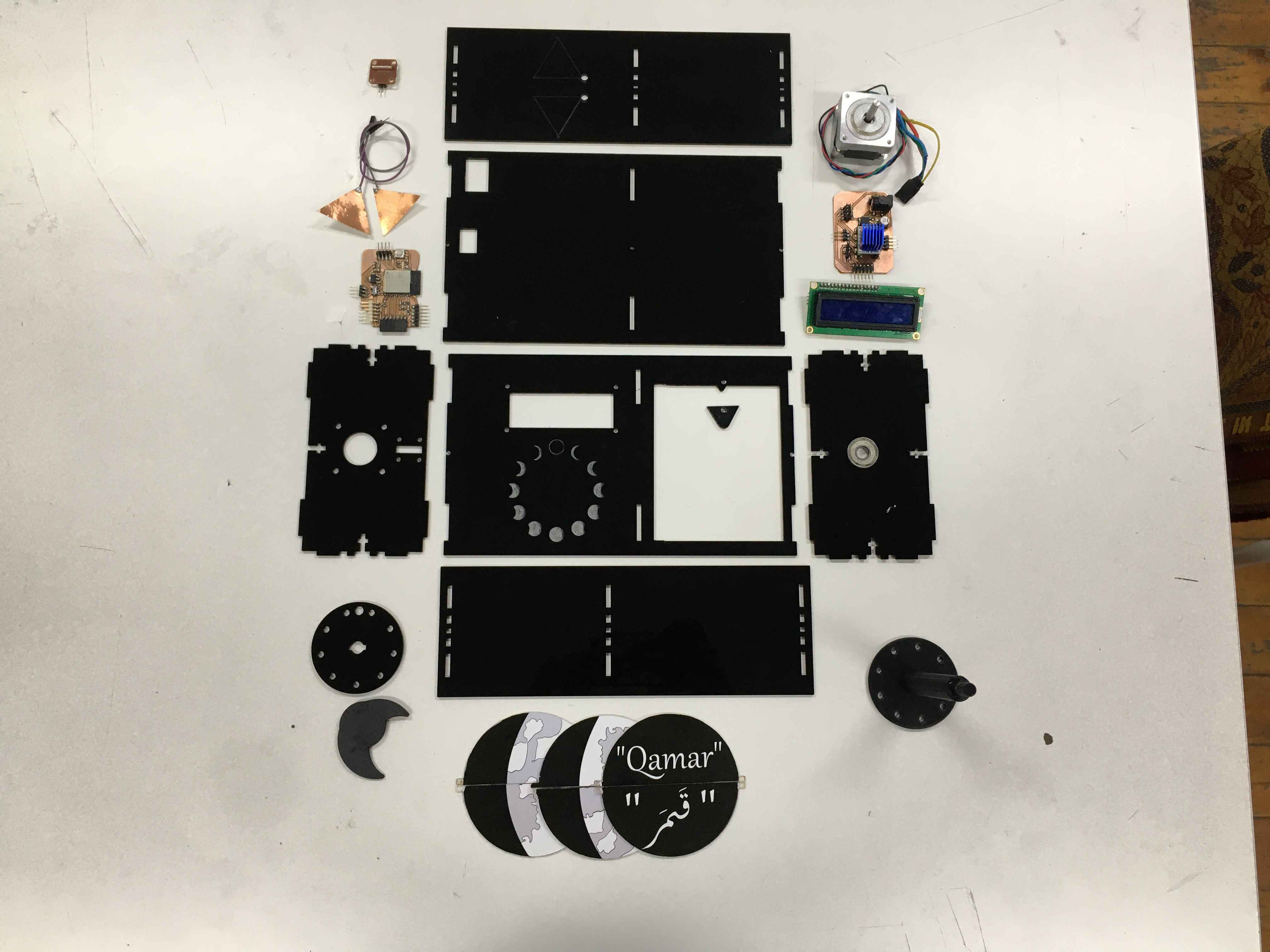
System parts image
Here I tried Homing and final test movements before closing the back and securing it with screws.
Final Look!
Challenges
- Chossing the right material for the flaps
- Power management issues ended up with two neopixels dead and one TMC dead. I apparently didn't factor in the amount of amperage the neopixesls needed!
- Issues with the power and not finding the right Voltage regulator in stock so my colleague Abdelrahman suggested I used the voltage regulator from unwanted H-bridge modules from our inventory. these regulators were 1.5A.
- TRACES!
- I had to reprint the shaft 3 times because tolerance issues and the stepper's design I grabbed from grabCAD didn't have the distinctive key in the shaft to help with securing it.
- Code: Making the stepper move slow enough for the reed sensor to detect the magnet on the shaft.
- Code: Moving the flaps smoothly required some altering the delay() function in the code.
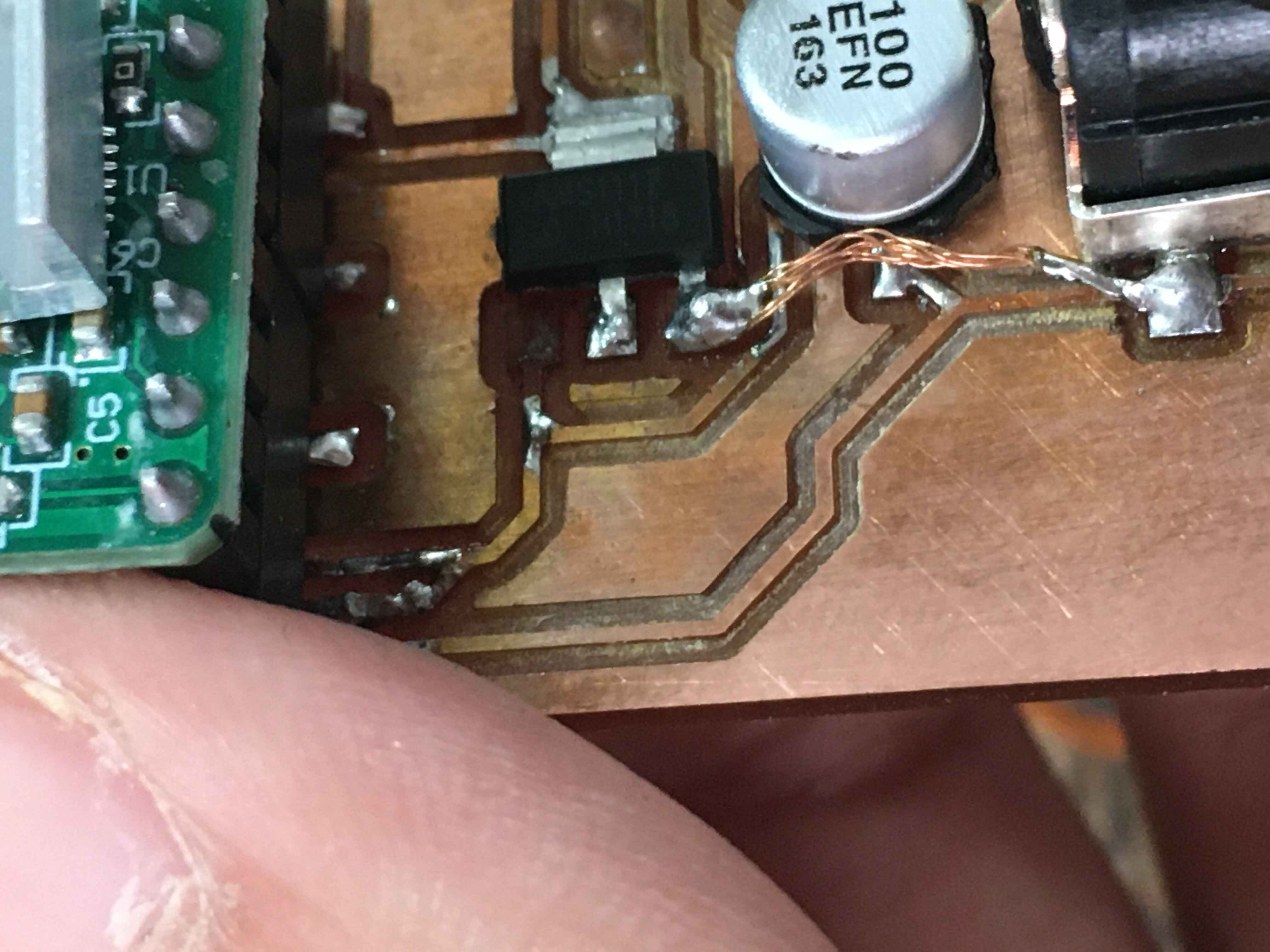
I apparently heated up the voltage regulator until I broke off its leg :""""]
Future Plans
Check my invention week for over the top plans!